Book Appointment Now


How Duty Cycle Determines Braking Resistor Size
A customer sent us a selection table for braking resistors for variable frequency drives (VFDs) and asked: ‘Our braking power is 140 kW; which row should we choose?’
The table lists options for duty cycles of 10 per cent, 20 per cent and 40 per cent. However, on mountainous stretches of road, their braking process can last up to 20 minutes. Clearly, none of the options in the table were suitable.
This is precisely the crux of this article. The duty cycle is essentially the conversion ratio between ‘peak power’ and the ‘actual thermal load on the resistor’. If this ratio is calculated incorrectly, the result will either be that you purchase a resistor with specifications far exceeding actual requirements (leading to waste), or that the resistor melts due to overheating during actual operation (even though it appears ‘fine’ on paper).
A one-sentence explanation of the duty cycle
Duty cycle = Braking time ÷ Total cycle time.
If the system is in a braking state for 1 minute out of every 10 minutes, the duty cycle is 10 per cent; if braking is continuous with no pauses, the duty cycle is 100 per cent.
For resistors, the mere ‘peak power’ is not important; what matters is the ‘average power’—that is, the product of peak power and the duty cycle. It is precisely this average power that is converted into heat, which must be dissipated via a cooling system.
Why can’t we simply calculate the power requirement using ‘peak power × time’?
This is precisely where people often fall into a misconception. A braking condition of 140 kW might seem to require a 140 kW resistor. However, if this condition lasts only 30 seconds within a 10-minute cycle, the average thermal load is actually only 140 × 0.05 = 7 kW. Provided the resistor’s resistance (in ohms) meets the peak power requirement, a resistor with a much lower power rating is entirely sufficient.
As mentioned in our selection guide on ‘Continuous Power versus Peak Power’, the selection process consists of two steps: first, determine the resistance value (U²/P) based on the peak power; then, determine the power rating (watts) based on the duty cycle. If either step is overlooked, the selection result will be inaccurate.
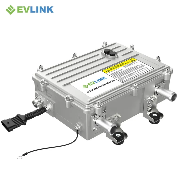
Take the HVH-R1402 liquid-cooled braking resistor as an example: its resistance at 25°C in a cold state is 2.24 ohms (tolerance ±10 per cent), with an operating voltage range of 450–850 V DC, supporting a power output of 140 kW for 20 minutes; It has an IP6K9K protection rating, an operating temperature range of –40 to +85°C, and is equipped with an NTC temperature sensor and a high-voltage interlock function.
The upper limit for the load factor in variable frequency drive (VFD) selection tables is typically 40%
In product catalogues for industrial variable frequency drives (VFDs), the upper limit for the load factor is generally around 40 per cent. This applies to equipment such as cranes, winches and conveyor belts—machinery that undergoes periods of inactivity following severe braking. The underlying assumption in such selection tables is that the resistors can cool sufficiently between two braking events.
However, electric buses and lorries do not always have the opportunity to rest. For example, a fully laden lorry travelling downhill may need to brake continuously for 20 minutes. In this case, the duty cycle is not 10 per cent or 40 per cent; throughout the entire descent, it is effectively operating at 100 per cent load.
If selection criteria based on a 40 per cent load factor are applied to operating conditions with a 100 per cent load factor, the rated capacity of the selected resistor will be less than half the actual thermal load. It may not fail on the first descent, but by the twentieth, as the insulation undergoes further thermal damage with each descent, failure will inevitably occur.
Special operating conditions for electric vehicles: 20-minute downhill braking
For this very reason, our HVH-R1402 model is rated for ‘140 kW sustained for 20 minutes’. This is not a peak power rating, but a thermal rating based on actual downhill conditions at 100 per cent load factor.
The calculation is straightforward: if the average power over 20 minutes is 140 kW, the resistor must dissipate 140 × 1,200 = 168,000 kJ of energy, which equates to approximately 47 kWh of energy converted into heat.
This heat is continuously dissipated via a liquid-cooling circuit (fitted with a DN32 connection and circulating coolant). If air-cooled resistors were used to achieve the same rated power, they would require enormous thermal capacity or an extremely high airflow rate, which is unfeasible within the limited space of a lorry chassis.
When a customer tells us, ‘Our route includes a 15-kilometre downhill section’, we do not simply consult the variable frequency drive (VFD) selection table. Instead, we ask the customer to provide the following data and base our selection on the most demanding continuous section of the route.
How to Estimate the Duty Cycle
There are three methods, listed from rough to precise:
Method 1: Gradient × Speed.
Identify the steepest continuous section of the route and the speed at which the lorry travels on that section.
Braking power ≈ mass × gravitational acceleration × gradient × speed.
For example, a 40-tonne lorry travelling at 60 kilometres per hour (i.e. 16.7 metres per second) on a 6 per cent gradient requires a continuous braking power of approximately:
40,000 × 9.81 × 0.06 × 16.7 ≈ 393 kW.
Dividing this power by the duration of the entire cycle yields the duty cycle.
Method 2: Energy ÷ Time.
If the difference in altitude is known, then energy = mass × acceleration due to gravity × height.
A 40-metric-tonne lorry descending 500 metres releases approximately:
40,000 × 9.81 × 500 ≈ 196 MJ.
If this descent takes 20 minutes, the average power is 163 kW. This is the power value that the braking resistor’s cooling system must be capable of handling.
Method 3: Measured current.
This is the most accurate and reliable method. Record the current through the chopper on the actual route, square it, multiply it by the resistance value, and then calculate the time-averaged value.
The formula is:
P_avg = R × I_rms².
If actual measurement data is available, please be sure to use it; if not, the estimation error in Method Two is typically within 20 per cent.
Regardless of the method used, the selection should be based on the most demanding section of the route, rather than the average of the entire route. This is because the braking resistor cannot ‘average out’ its temperature by operating on gentle sections.
Common misconception: Selecting components based solely on average values whilst ignoring peak values
This is a typical error. Some people calculate an average power of 30 kW and purchase a 30 kW braking resistor, whilst overlooking the fact that the chopper may still be subjected to a peak power of 140 kW. In this case, the resistance value (in ohms) is set incorrectly—it is too high, resulting in an inability to absorb the peak power at the DC bus voltage.
Peak power determines the resistance value (ohms), whilst the duty cycle determines the rated power (watts). These two checks relate to two distinct values. Our ‘Resistance-Voltage Matching Guide’ covers peak power considerations, whilst this article focuses on thermal performance. The resistor must pass both checks.
If a resistor passes the peak power check but fails the duty cycle check, it will overheat and rise in temperature (albeit slowly); if the resistor passes the duty cycle test but fails the peak test, it will be unable to provide sufficient braking force during the first braking manoeuvre.
Although the failure symptoms differ, the root cause is the same: only half the factors were considered during selection.