Book Appointment Now


Continuous vs. Peak Power: What Really Sizes a Braking Resistor
An electrical engineer sent us a quotation request stating ‘peak 300 kW’, whilst our data sheet specifies ‘rated 140 kW’. He asked: Which figure should be used as the basis for the design? Is 140 kW actually sufficient?
In the field of variable frequency drives (VFDs), these are actually two distinct issues: peak power determines the resistance value, whilst the duty cycle determines the rated power. If the two are conflated into a single figure, you will either waste money purchasing an oversized resistor or burn out an undersized one. This is the most costly misunderstanding in braking resistor selection, yet almost all online formula guides only answer half the question, thereby exacerbating this confusion.
Peak power determines ohms; duty cycle determines watts
This single sentence sums up the entire text.
Resistance value is a choice at the electrical level: can the chopper withstand the corresponding current? Can the resistor dissipate the required power?
Rated power is a choice at the thermal design level: over the entire braking duration, can the resistor convert this power into heat and dissipate it?
These are two independent selection steps. The industry has always treated them separately; it is simply that buyers have gradually overlooked this distinction.
Peak power determines only the resistance value, not the heat dissipation capacity
The resistance value is calculated from the peak power:
R = U² ÷ P_peak
This formula helps determine the electrical selection range: the resistance must be low enough to allow the chopper to absorb the full braking power; at the same time, it must be high enough to prevent the current from damaging the switching devices.
We have explained this range in detail in our resistor value calculation guide. Once the range is determined, the resistor selection process is complete.
The rated power requires a separate calculation, for which the drive industry has a standard calculation procedure. Stevens Drives’ ‘BrakeResCalc’ documentation sets this out clearly:
- Peak current = √(peak power ÷ resistor value)
- Continuous current = peak current × duty cycle
- Resistor power rating = peak power (kW) × duty cycle × 0.5, where 0.5 is a conservative safety factor
Schneider Electric’s Braking Resistor FAQ also expresses the same principle in the third selection rule: determine the resistor’s power rating based on the average braking power, rather than the peak power, depending on the load and duty cycle.
Let us consider an actual product. Our HVH-R1402 has a cold resistance value of 2.24 Ω (25 °C, tolerance ±10 per cent), is suitable for DC systems operating at 450–850 V, and has a continuous power rating of 140 kW, sustainable for 20 minutes.
At 850 V, its instantaneous electrical power capacity is:
850² ÷ 2.24 ≈ 323 kW
For the same resistor, there are two figures:
- 323 kW: electrical power capacity
- 140 kW: thermal power rating
This discrepancy is not a contradiction; rather, it is the crux of the matter. One figure answers the question ‘Can it brake?’, whilst the other answers ‘Can it withstand the load?’.
Tolerances will also alter this range. At the two extremes of the cold-state resistance tolerance of ±10 per cent:
- 2.016 Ω corresponds to a peak power capacity of approximately 358 kW
- 2.464 Ω corresponds to a peak power capacity of approximately 293 kW
For the same product and the same data sheet, there is a difference of 65 kW. Therefore, it is essential to verify both extremes of the tolerance range, rather than merely checking the nominal value.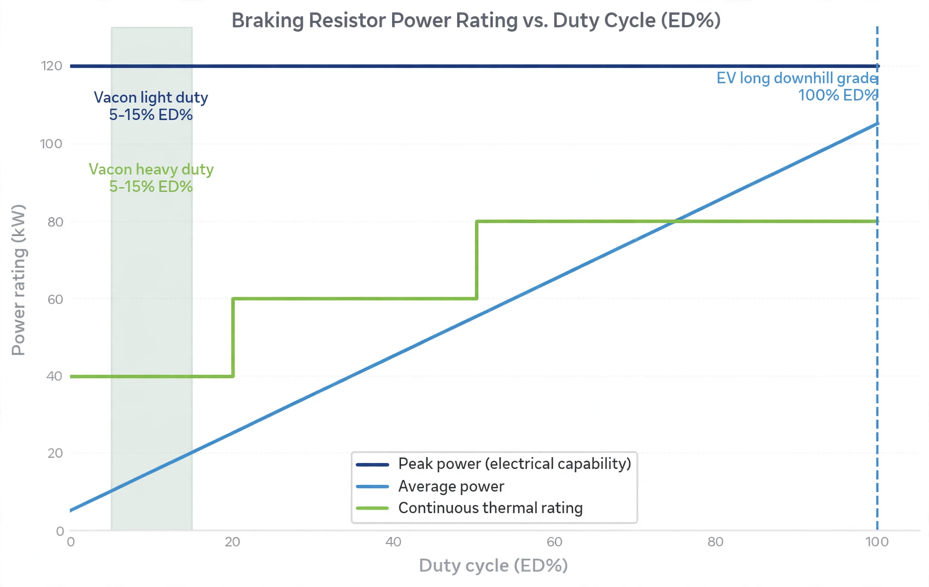
Duty cycle is the conversion ratio between peak power and average power
The duty cycle, D, is the proportion of the entire cycle during which the resistor actually dissipates energy:
D = Braking time ÷ Cycle time
A D value of 1 indicates continuous dissipation. Typical industrial braking occurs under intermittent conditions, where D is far less than 1.
The variable-frequency drive industry has even established specific terminology for this. Vacon’s braking resistor manual defines a heavy-duty condition as follows: over a 120-second cycle, the resistor operates at full power for 3 seconds, then gradually decelerates to zero over 7 seconds; a light-duty condition, by contrast, involves a gradual deceleration from full power to zero within 5 seconds.
Let’s look at this again: in the drive industry, ‘heavy-duty’ means only a few seconds of operating time. The entire ED% (duty cycle) system is based on the assumption that ‘braking time is very short’.
From this, we can directly derive the practical selection rule: determine which ED% bracket your duty cycle falls into, then purchase the rated power specification corresponding to that bracket.
If you purchase a braking resistor based on peak power for intermittent operation, you will be paying for thermal capacity that you will never actually use. Conversely, if you select a resistor rated for 5% ED for continuous operation, it will overheat and burn out. This is not a fault in manufacturing quality, but rather the result of selecting the wrong specification during the selection process.
Special circumstances for electric vehicles: Downhill driving pushes the duty cycle to 100%
At this point, the assumptions made in the variable-frequency drive sector no longer hold true.
A forum in the drive industry bluntly expressed its prevailing view: braking resistors ‘rarely require a 100 per cent duty cycle, as regenerative braking typically lasts only a few seconds’.
This statement holds true for factory conveyors. However, for electric mining trucks that brake continuously for 20 minutes on a long downhill gradient, such an assumption could prove extremely costly.
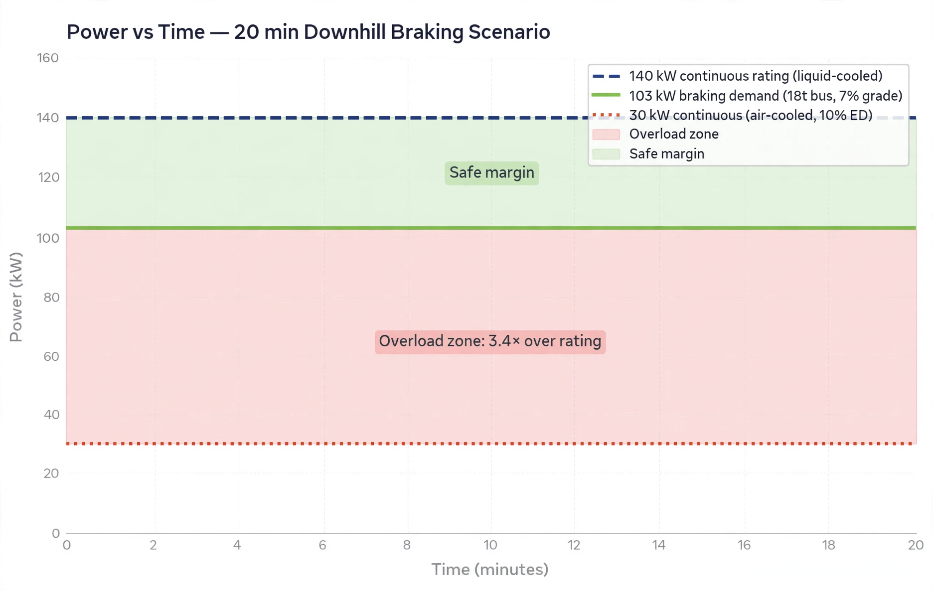
Take the 18-tonne coach from our selection guide as an example: travelling at 30 km/h on a 7 per cent gradient requires approximately 103 kW of braking power. A continuous 20-minute descent corresponds to the following energy:
103 kW × 1,200 seconds ≈ 34 kWh
All of this energy is converted into heat and must be dissipated somewhere; at this point, the duty cycle is effectively close to 100 per cent.
Now let us consider the selection of rated power. Compared to the HVH-R1402’s continuous rated power of 140 kW, 103 kW represents approximately 74 per cent of the load, which would allow for relatively comfortable operation throughout the day.
However, for a typical air-cooled resistor—assuming a peak rated power of 300 kW and a duty cycle of 10 per cent (ED), which equates to a continuous power of approximately 30 kW (for illustrative purposes)—the same 103 kW would represent a 3.4-fold overload.
It would not fail after a year, but could fail within minutes. This is not a quality issue, but rather a misunderstanding of the meaning of the rated parameters. The resistor has never been rated to withstand the operating conditions actually imposed upon it.
Therefore, the first question when selecting a braking resistor for an electric vehicle is not ‘how high is the peak power?’, but rather:
‘What is the duration of your longest continuous braking session?’
All other assessments stem from this answer.
What information do we require?
If you wish us to verify the power specifications, please provide the following four pieces of information; our engineers will then propose a configuration based on these:
- Braking power: peak kW, continuous kW, and maximum continuous duration.
- Operating conditions curve: gradient, vehicle speed and duration of the longest downhill section.
- DC bus voltage range.
- Cooling conditions: What conditions can the vehicle’s cooling circuit provide?
Frequently Asked Questions
Why does the same resistor have both a peak rating of 323 kW and a rated power of 140 kW?
Because they measure different things.
323 kW is the instantaneous electrical power capacity, i.e. the power that this resistor can absorb at any given moment. 140 kW is the continuous thermal power rating, i.e. the power that it can continuously convert into heat and dissipate over a period of 20 minutes.
One relates to the chopper’s ability to withstand the load, whilst the other relates to the resistor’s ability to withstand it.
What ED% should be selected for mountainous gradients?
Selection should be based on the longest single continuous braking event.
A 20-minute downhill driving scenario for an electric vehicle is, in practice, close to 100 per cent duty cycle. The rated power should be determined based on continuous operation, rather than applying ED% tables designed for intermittent factory braking.
Does PWM alter the calculation method?
PWM control of the braking chopper divides the instantaneous electrical power into a controllable average power. This is how the thermal power rating can be met whilst peak power is present.
The permissible range of resistance values remains unchanged; what changes is the average power that the resistor must dissipate.
Is liquid cooling always necessary?
This depends on the duty cycle.
Air cooling may be used for intermittent operation with long braking intervals and sufficient rest periods. However, during a continuous 20-minute descent at high power, liquid cooling is no longer an optional extra: throughout the entire process, heat must be dissipated from the resistor at a rate no slower than the rate at which it is generated.
To be on the safe side, can I simply choose a higher rated power?
Yes, and many buyers do indeed do this.
However, increasing the rated power does not alter the permissible range of resistance values; the resistance must still fall between Rmin and Rmax.
A higher rated power means greater volume, greater weight and higher costs. You should select the wattage based on actual operating conditions, rather than on your level of anxiety.
Please provide us with the peak braking power and the maximum continuous braking time. We will match the appropriate resistance range to the operating conditions and advise you honestly as to whether an air-cooled solution is sufficient.