Book Appointment Now


PRODUCTS | INTEGRATED THERMAL CONTROL
Three-in-One EV Thermal Management Controller
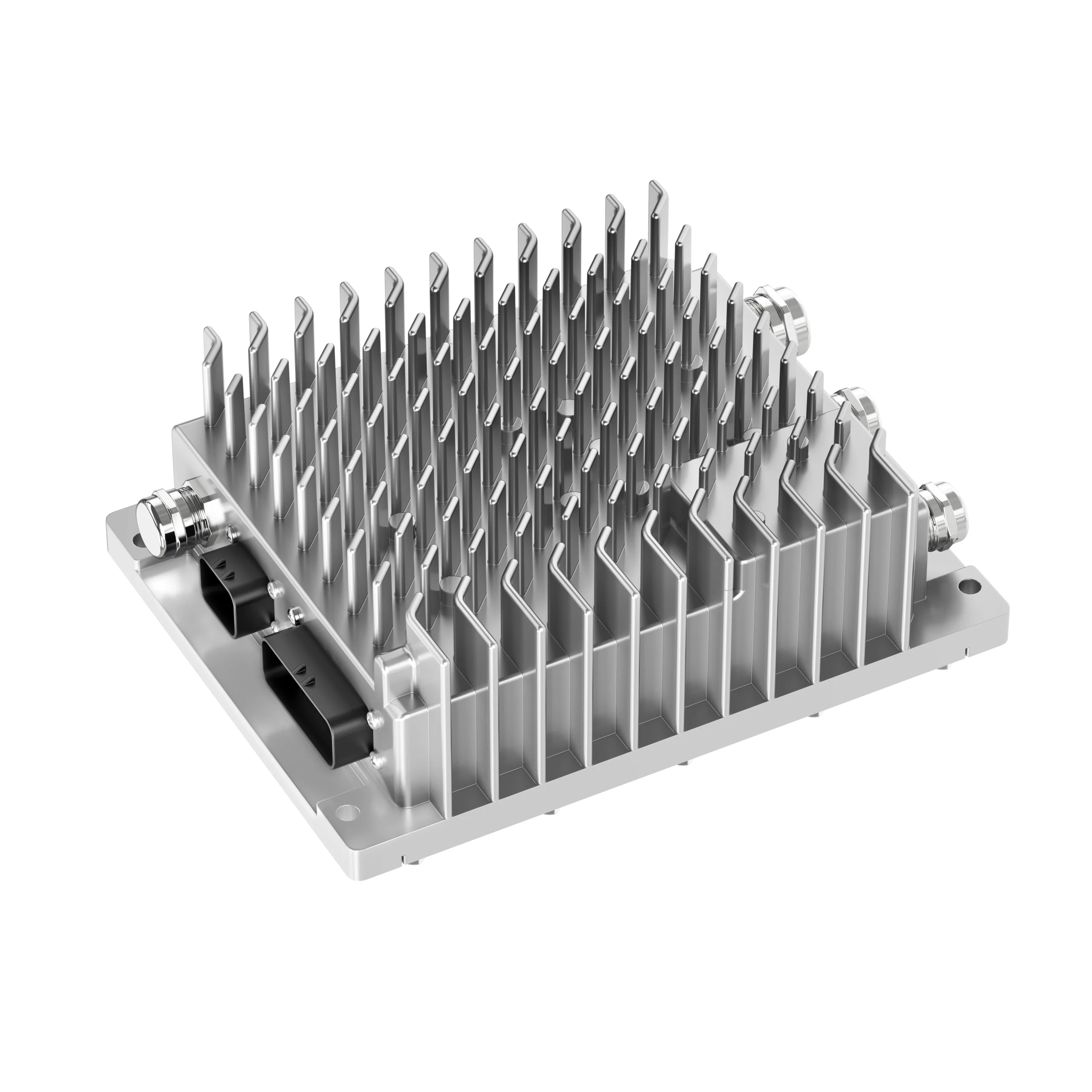
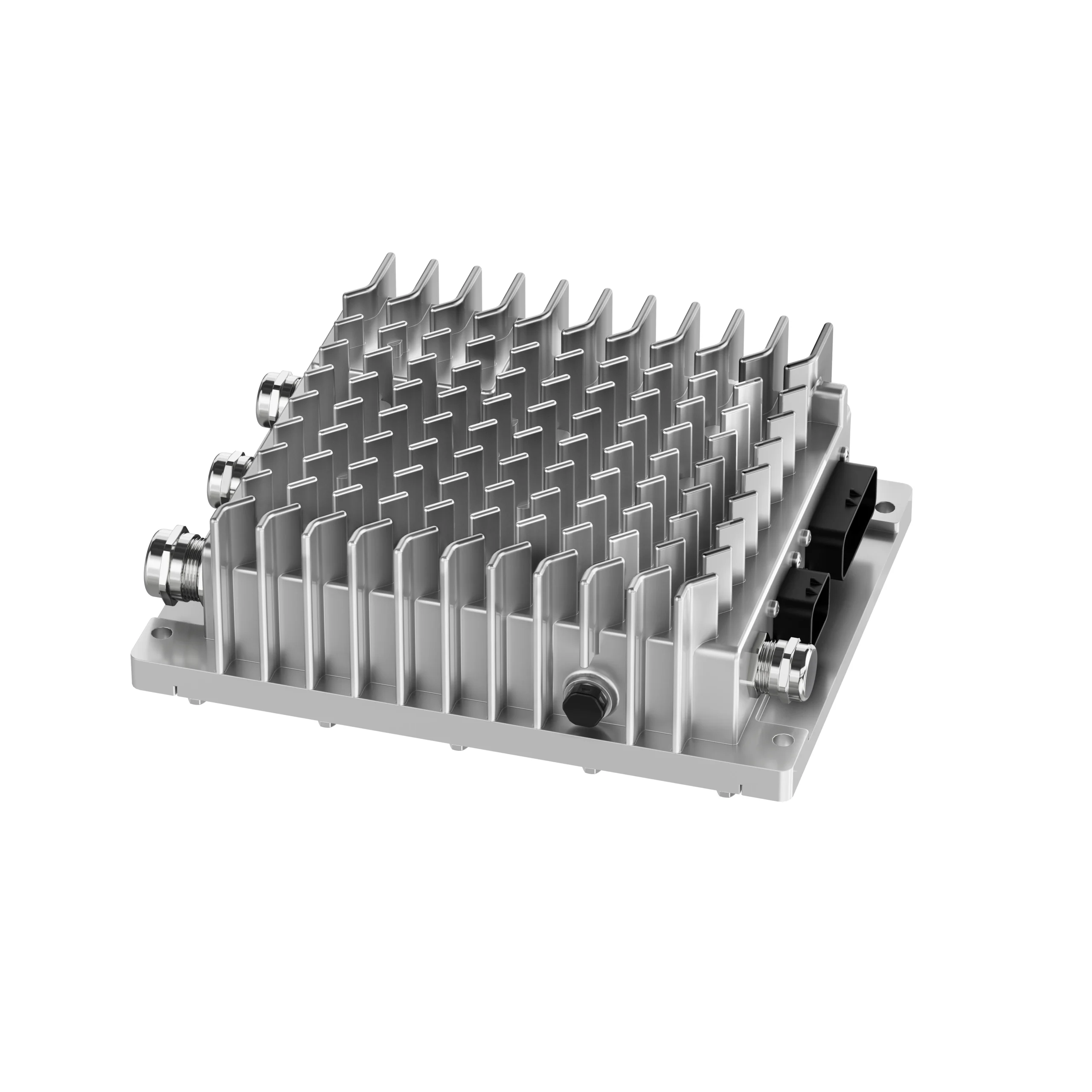
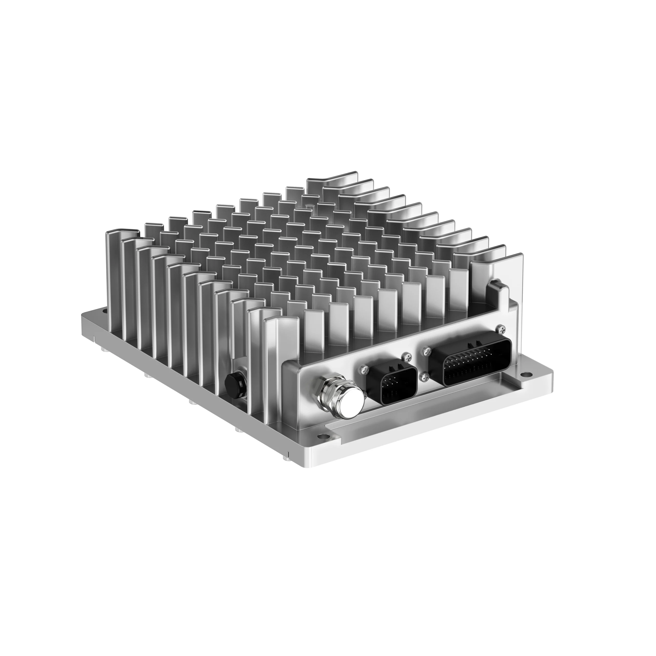
EVLINK’s Three-in-One Thermal Management Controller integrates three control units into a single housing: a DCAC electric compressor controller, a refrigeration system ECU, and a high-voltage PTC controller. Built for 600V and 800V electric commercial vehicle platforms, it centralizes control of the compressor, expansion valve, cooling fan, and PTC heating — replacing three separate controllers with one IP67-rated unit.
600 / 800 V
Nominal platforms
≥ IP67
Control box rating
CAN 2.0
Vehicle communication
THREE FUNCTIONS. ONE CONTROL ARCHITECTURE.
Integrated Thermal Management Control
Some EV thermal architectures use separate controllers for the electric compressor, refrigeration system and high-voltage PTC heating. The housings, wiring, power supplies and communication interfaces depend on the vehicle design.
The EVLINK three-in-one controller combines all three into a single unit:
01
DCAC Compressor Controller
5–10 kW, adjustable to the application
02
Refrigeration System ECU
Coordinates the refrigeration circuit
03
High-Voltage PTC Controller
PTC power: 8 kW + 24 kW battery heating
One housing. One 24V supply. One set of CAN interfaces. Fewer parts, fewer interfaces, fewer failure points.
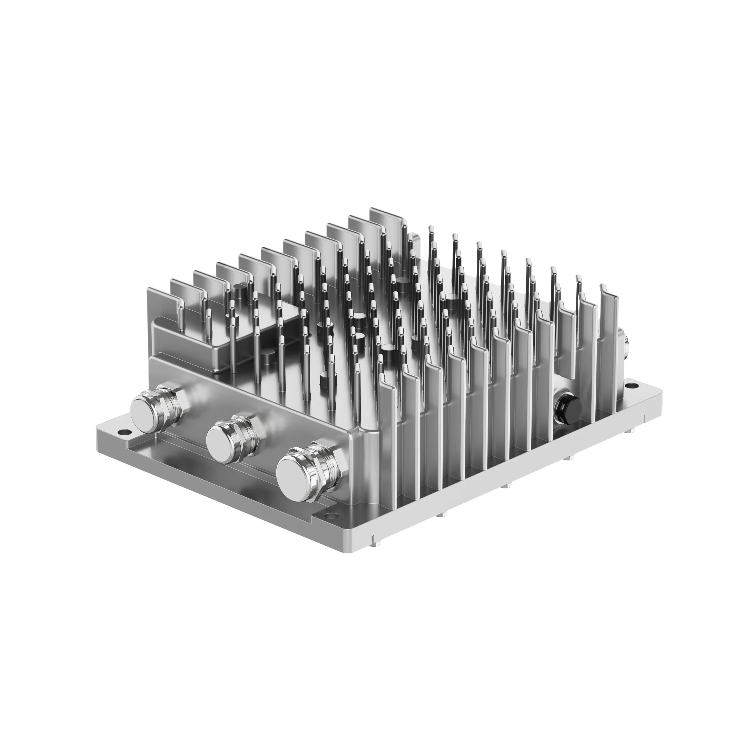
Product Views
Three Control Loops, One Controller
Thermal management is won or lost in the control strategy. The three-in-one controller runs three coordinated control loops:
Loop 1 — Compressor speed follows water temperature. Compressor speed tracks the system water temperature against the target temperature: as water temperature rises, speed increases; as it falls, speed decreases. Continuous speed regulation avoids the energy waste and mechanical stress of frequent start-stop cycling.
Loop 2 — Expansion valve follows superheat. The electronic expansion valve opening follows superheat at the evaporator outlet: higher superheat opens the valve further, lower superheat closes it. Holding superheat around 5 K is common industry practice, calibrated per project. Too little superheat risks liquid refrigerant reaching the compressor; too much wastes evaporator capacity.
Loop 3 — Fan follows condenser pressure. The condenser fan is controlled against condenser high-side pressure. As an example, the fan may start when pressure reaches about 13 bar; start/stop pressure points and the speed curve are calibrated to the vehicle project.
Because the three loops interact — a change in compressor speed shifts superheat, which shifts condenser pressure — running them in one controller means shared sensor data and no CAN latency between loops. The CAN protocol, CAN IDs, baud rate, and control logic can all be customized per project.
How the three loops work together in detail: EV Thermal Management Control Strategy: How Compressor, Expansion Valve and Fan Work Together
From Three Boxes to One: What Integration Removes
The following illustrates one possible comparison with three separate controllers. Actual housings, wiring, communication and validation requirements depend on the vehicle design:
| Three separate controllers | Three-in-one controller | |
|---|---|---|
| Housings | 3 sealed housings | 1 housing, rated ≥ IP67, sealed once |
| Low-voltage supply | 3 × 24V feeds | 1 × 24V feed (16–32V DC) |
| CAN nodes | 3 nodes to integrate and calibrate | 1 node set |
| Wiring | HV + LV + CAN harnesses × 3 | Single harness set |
| Cooling design | 3 thermal designs | Shared open-fin natural cooling |
| Spares & diagnostics | 3 part numbers, 3 diagnostic interfaces | 1 of each |
Fewer external interfaces may simplify integration. Actual wiring, validation scope and reliability depend on the selected vehicle architecture and must be confirmed for the project.
Three Separate Controllers vs. One Integrated Unit
A vehicle may use separate compressor, refrigeration ECU and high-voltage PTC controllers. The number of suppliers, connectors and harnesses depends on the selected architecture.
Our three-in-one unit puts all three control loops in a single 6 kg housing. The compressor output adjusts from 5 to 10 kW to match the cooling load, and the heating side runs two channels: 8 kW of PTC heating plus a 24 kW battery heating channel. One CAN node to integrate, one mounting point, one part number to stock. The unit is rated from −40°C to +65°C, so it lives where the vehicle lives.
Honest caveat: if your platform already has a qualified compressor controller you are happy with, keep it. Integration pays when you are designing or redesigning the thermal system, when harness space is tight, or when your team is tired of chasing faults across three vendors. That is most new commercial EV programs we see, but it is not every program.
MOQ runs from 10 to 50 units depending on configuration, with a 15-day lead time. Send us your compressor and heater specs and we will confirm the configuration that fits.
INTEGRATION CONFIGURATION
How the Three-in-One Controller Fits the Vehicle
High-voltage input, 24 V control power and CAN communication are coordinated with three thermal-control functions.
VEHICLE INPUTS
600 V / 800 V Battery
24 V Low-Voltage Supply
CAN 2.0 Communication
THREE-IN-ONE CONTROLLER
DCAC COMPRESSOR CONTROL
REFRIGERATION SYSTEM ECU
HIGH-VOLTAGE PTC CONTROL
ELECTRIC
COMPRESSOR
REFRIGERATION
SYSTEM
HIGH-VOLTAGE
PTC HEATER
TECHNICAL PERFORMANCE
Parameter Specifications
Values below are based on the product parameter information supplied by EVLINK. Final selection remains configuration- and project-dependent.
Technical Performance
Parameter Specification
Integration Configuration
DCAC compressor controller + refrigeration system ECU + high-voltage PTC controller in one unit
Rated DC Voltage
600V DC / 800V DC
Controller Input Voltage Range
250–750V DC / 600–1000V DC
Battery Nominal Voltage
600V DC / 800V DC
Battery Operating Voltage Range
400–750V DC / 600–1000V DC
Control Box Protection Rating
≥ IP67
Cooling Method
Natural cooling (open-fin design; air velocity ≥ 3.5 m/s at mounting point)
Communication protocol
CAN 2.0 (protocol, CAN ID, baud rate, and control logic customizable per project)
Low-voltage control power supply
24V DC (16–32V DC)
Pre-charge circuit
Integrated pre-charge resistor circuit
Operating ambient temperature
-40℃ to +65℃
Mounting orientation
Vertical mounting (layout designed for easy installation and maintenance)
Weight
6 kg ±10%
Dimensions
Approx. 280 × 200 × 95 mm (varies by vehicle model)
| Parameter | Value |
|---|---|
| Operating ambient temperature | −40°C to +65°C |
| Weight | 6 kg ±10% |
| Compressor power | 5–10 kW |
| PTC power | 8 kW + 24 kW battery heating |
What are the core controller specifications?
The three-in-one controller has an operating ambient temperature range of −40°C to +65°C and a weight of 6 kg ±10%. The compressor power range is 5–10 kW. The PTC power specification is 8 kW plus 24 kW for battery heating. Confirm the selected load configuration and released interfaces with EVLINK before integration.
COOLING REQUIREMENT
Natural Air Cooling Requires a Defined Vehicle Air Path
The latest design uses natural air cooling instead of a dedicated controller liquid-cooling connection.
The installation area must provide an air speed of at least 3.5 m/s and the same airflow speed as the condenser. EVLINK engineering should review the real mounting position, ducting, condenser location, surrounding heat sources and service clearances before release.
≥ 3.5 m/s
Required air speed at the controller installation area
Same as Condenser
Airflow condition stated in the latest technical material
LATEST DESIGN ADVANTAGES
Integrated for Commercial-Vehicle BTMS Liquid-Chiller Systems
The controller is built around commercial-vehicle BTMS liquid-chiller systems. It coordinates battery cooling and heating loops, cabin climate, and power electronics thermal management from one unit — on 600V and 800V platforms.
It suits city buses, coaches, trucks, and off-highway electric machinery. The voltage platform, compressor matching, CAN protocol, and fan control curves are configured per vehicle project, so the same controller architecture adapts across commercial vehicle types.
01
Integrated Architecture
Combines DCAC compressor control, refrigeration ECU and high-voltage PTC control to simplify the system boundary and external connections.
02
SiC Power Devices
The latest design uses SiC power devices as the stated route to higher voltage capability and lower heat generation.
03
Metal Cable Glands
Metal cable-gland connections are used as the stated route to stronger sealing and connection reliability.
04
Natural Air Cooling
Removes the controller liquid-cooling connection, subject to the defined ≥3.5 m/s installation airflow requirement.
05
Compact Vertical Package
The open-fin, vertically mounted package is designed to save installation space and support service access.
06
600 V / 800 V Platforms
Supports two rated vehicle voltage platforms within the listed controller and battery operating ranges.
INTEGRATION REVIEW
Four Interfaces Must Be Confirmed Before Release
A nominal voltage match alone is not sufficient for controller selection.
Review the compressor, expansion-valve and fan control strategy alongside the integrated controller cost review. Confirm which functions remain with the vehicle controller and which belong to the selected thermal management controller.
01
High-Voltage Review
Confirm battery nominal voltage, minimum and maximum operating voltage, current limits, pre-charge strategy, interlock and protection coordination.
02
Low-Voltage & CAN Review
Confirm 24 V supply conditions, wake/sleep behavior, CAN baud rate, messages, states, faults, diagnostics and control ownership.
03
Load & Interface Review
Confirm compressor and PTC electrical requirements, refrigeration-control boundary, connectors, pin assignments and harness responsibility.
04
Installation & Airflow Review
Confirm vertical mounting, envelope, fixing points, ≥3.5 m/s air speed, condenser airflow, ambient temperature, surrounding heat, sealing boundary and service access.
APPLICATION AREAS
Built Around Commercial and Off-Highway EV Integration
Each platform requires a separate review of voltage, loads, control responsibility, packaging and validation.
BTMS Liquid Chiller
Primary integration route shown in the latest material for commercial-vehicle battery thermal management.
Electric Bus
Coordinated HVAC and coolant-heating control for route-based commercial operation.
Electric Truck
Thermal control integration for payload, grade, charging and depot duty cycles.
Electric Mining Truck
Controller integration for harsh environments, sustained haul loads and serviceability.
Construction Machinery
Thermal coordination for variable work cycles, vibration and restricted installation space.
PROJECT INPUTS
Information Required for Controller Selection
Provide the system inputs before model confirmation, interface release or software/CAN alignment.
Unknown conditions should be recorded as assumptions and closed before design release.
- Vehicle or equipment platform and target market
- Battery nominal, minimum and maximum operating voltage
- Electric compressor model and electrical requirements
- PTC heater model, voltage, power and control requirements
- Refrigeration-system control architecture and ECU boundary
- 24 V supply, wake/sleep and ignition conditions
- CAN database, baud rate, messages and diagnostic requirements
- HV/LV connectors, pin assignment and harness responsibility
- Installation envelope, vertical mounting and service access
- Measured air speed, condenser airflow and surrounding heat sources
- Ambient temperature, vibration, ingress and heat-source conditions
- Pre-charge, interlock and protection coordination
- Prototype quantity, validation plan and project timing
ENGINEERING WORKFLOW
From Vehicle Requirement to Released Controller Configuration
Each step closes a defined integration risk before the next commitment.
01
Requirement Review
Confirm voltage, loads, architecture, interfaces, communication, environment and timing.
02
Configuration Selection
Match the requirement to the 600 V or 800 V route and identify open technical items.
03
Interface Definition
Release the agreed HV/LV, CAN, load, mounting, connector and responsibility boundary.
04
Prototype Integration
Support installation, commissioning, communication checks and issue tracking.
05
Validation & Release
Verify the approved configuration under agreed conditions before production release.
BEFORE QUOTATION OR RELEASE
Project-Specific Items That Still Require Confirmation
These items are intentionally not invented or generalized on this page. They must come from the selected product drawing, datasheet, CAN document and validation record.
Output Ratings
Compressor and PTC output current, power and channel ratings.
Mechanical Data
Envelope dimensions, mounting-hole drawing, mass tolerance, cable-gland definition and connector access.
Electrical Interfaces
Connector part numbers, pinout, interlock and harness definition.
CAN Definition
Baud rate, message IDs, commands, feedback, states, faults and diagnostics.
Protection Strategy
Over/under-voltage, over-current, temperature, isolation and fallback behavior.
Cooling & Validation Evidence
Airflow mapping at the installation point plus applicable EMC, insulation, vibration, environmental and customer-specific test records.
FREQUENTLY ASKED QUESTIONS
Three-in-One Controller FAQ
Technical answers should always be read together with the selected configuration and released project documentation.
It integrates the DCAC compressor controller, refrigeration system ECU and high-voltage PTC controller in one compact control unit.
The supplied technical material identifies SiC as the power-device route intended to increase voltage capability and reduce heat generation. Final device configuration and performance evidence remain project-specific.
The installation area requires an air speed of at least 3.5 m/s and the same airflow speed as the condenser. This condition must be checked in the real vehicle air path.
The latest material identifies metal cable glands as the connection route intended to improve sealing and connection reliability. Final gland, cable and installation details must follow the released drawing.
The supplied specification covers 600 V DC and 800 V DC nominal platforms. The applicable input and battery operating ranges must be matched to the selected configuration.
The latest source positions it for commercial-vehicle BTMS liquid-chiller systems, subject to confirmation of voltage, compressor, PTC, CAN, airflow, mounting and validation requirements.
Yes. The controller can be adapted to customer-specified compressors. Provide the compressor’s technical parameters and motor parameters, and we will configure the control accordingly.
Yes. The CAN protocol, CAN IDs, baud rate, and control logic can all be customized per project.
MOQ is 10 or 50 units. Standard lead time is 15 days.
Three control functions in one unit: the electric compressor controller, the refrigeration system ECU and the high-voltage PTC controller. Instead of three separate boxes with separate harnesses, the vehicle gets one controller, one CAN node and one mounting point.
The compressor output is adjustable from 5 to 10 kW depending on the cooling load. On the heating side there are two channels: 8 kW for PTC cabin and system heating, and a separate 24 kW channel dedicated to battery heating.
Minimum order runs from 10 to 50 units depending on the configuration, and standard lead time is 15 days. The unit weighs 6 kg and is rated for −40°C to +65°C ambient, so it suits buses, trucks and off-highway vehicles without a special enclosure.
RELATED PRODUCTS
Complete the Thermal Management Architecture
Connect controller selection with the actual compressor, PTC heater and battery thermal-management requirements.
High Voltage Coolant Heater
Review heater voltage, power, coolant and control requirements.
TALK TO EVLINK ENGINEERING
Define the Right Three-in-One Controller Configuration
Every vehicle project has a different voltage platform, compressor choice, and thermal target. Share your vehicle type, platform voltage, compressor parameters, and operating climate — we will define a controller configuration with honest trade-offs, including telling you when integration is not the right answer for your project.