Book Appointment Now



Thermal management is won or lost on control strategy, not on components. The best electric compressor in the world, driven by a poor control logic, will still waste energy, wear itself out, and leave the battery outside its comfort zone. Yet most explanations of EV thermal control sit at two unhelpful extremes: academic papers full of control-theory mathematics, or hobbyist projects wiring an Arduino to a relay.
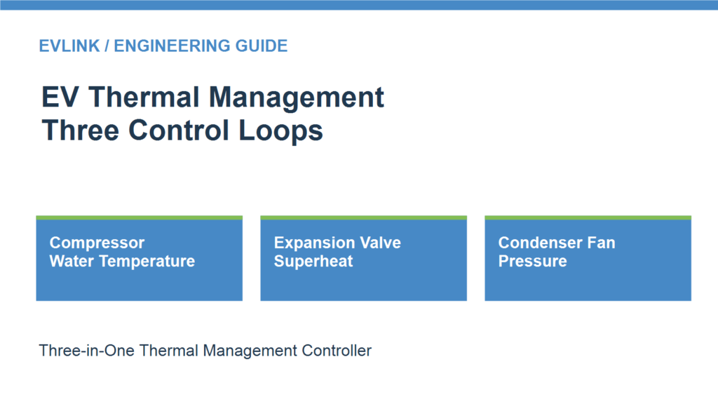
This article takes the middle path a working engineer actually needs. An EV thermal system has three actuators that matter — the compressor, the electronic expansion valve, and the fan — and each one listens to a different signal. We explain the three control loops in plain language: what each loop measures, what it drives, and why the loops belong together.
Before the loops, the roles. Each actuator in the refrigerant circuit controls exactly one thing:
This three-way split is not just our product architecture. Peer-reviewed demand-based heat-pump control research (MDPI) structures its baseline control algorithm the same way: a PI loop driving compressor speed, a PI loop holding evaporator-outlet superheat via the expansion valve, and a PI loop driving fan airflow. We mention this because it confirms the framing — we will not be deriving any transfer functions here. What matters for a system designer is simpler: three actuators, three signals, three loops.
The logic: compressor speed is regulated against the system water temperature and the target temperature. Water temperature rises above target → speed increases. Water temperature falls → speed decreases.
Why water temperature? Because it is the most direct available proxy for the system’s cooling demand. The water (or water-glycol) circuit is what actually carries heat away from the battery and power electronics; its temperature tells you, moment by moment, how much cooling the system is asking for. Regulating against it keeps cooling output proportional to demand: full speed only when the system genuinely needs full cooling.
The alternative — and the mistake this loop exists to prevent — is on/off cycling: running the compressor at full speed until some threshold trips, then shutting it off, then restarting. Every start draws an inrush current, wears the bearings, and dumps a slug of unconditioned refrigerant into the circuit. Continuous speed modulation avoids all three. The energy saving is real but almost secondary; the reliability argument alone justifies the loop.
The engineering takeaway: size the compressor for the worst case, but let the water-temperature loop decide how much of that capacity to use at any moment. Capacity on demand, not capacity by default.
The logic: the expansion valve opening is controlled against superheat. Superheat high → opening increases. Superheat low → opening decreases.
Superheat in one sentence: the difference between the refrigerant temperature at the evaporator outlet and the saturation temperature at which it would begin condensing — in other words, how much safety margin of “fully vapor” you have before liquid starts appearing where it shouldn’t.
Why it matters: superheat is the single most safety-critical variable in the circuit, and the consequences of getting it wrong run in both directions:
Industry practice: holding superheat around 5 K at the evaporator outlet is a common target in published control research (MDPI demand-based control designs use exactly this value). Treat it as a starting point, not a specification — the right target is calibrated per project, per refrigerant, and per operating envelope.
The advanced technique worth knowing: the best implementations don’t rely on superheat feedback alone. A known approach (described in patent CN103245154B for automotive electronic expansion valve control) uses compressor speed as a feedforward signal to pre-adjust the valve opening, then layers superheat feedback on top for fine trimming. When the compressor ramps up, the valve already knows more refrigerant is coming and opens preemptively, instead of waiting for superheat to drift and then correcting. The feedback loop then only handles small residuals — smaller corrections, less oscillation, tighter control.
This is also the clearest technical argument for putting the compressor and EXV loops in the same controller: feedforward needs the compressor’s speed signal in real time. Across two separate controllers, that signal travels over CAN — with latency, with message scheduling, with calibration split across two teams. Inside one controller, it is shared memory. The loop coordination that makes feedforward work is an architectural property, not just a software feature.
The logic: the condenser fan is controlled against the condenser high-side pressure. As an example, the fan may start when high-side pressure reaches about 13 bar; the start/stop pressure points and the speed curve are calibrated per vehicle project.
Why pressure, not temperature? High-side pressure directly reflects the condensing load — how much heat the condenser must reject right now. It responds faster than temperature sensors, which lag behind the thermal mass of the heat exchanger. Pressure is the leading indicator; temperature is the trailing one. Controlling the fan from pressure means the fan reacts to the load as it develops, not after the heat has already built up.
The calibration space: the example 13 bar figure is exactly that — an example. Real projects set their own start and stop pressures and their own fan speed curves against the vehicle’s condenser sizing, ambient conditions, and noise requirements. A bus operating in 45℃ ambient needs a different pressure map than the same hardware in a temperate climate. This is normal project calibration work, and any serious controller supplier should support it.
Note the pattern across all three loops: each actuator listens to the variable that most directly represents its own job — the compressor to cooling demand (water temperature), the valve to refrigerant state (superheat), the fan to heat-rejection load (condenser pressure). No loop is guessing from a proxy two steps removed.
The three loops are coupled, and that coupling is the whole argument:
Every loop’s output is another loop’s disturbance. When the loops live in separate controllers, they coordinate over the vehicle CAN bus: messages queued, latencies of tens of milliseconds, calibration split across suppliers who each tune their own loop in isolation. It can be made to work — the industry has done it for years — but the coordination is always fighting the architecture.
Inside one integrated controller, the loops share sensor data directly, run on a unified timing base, and the feedforward paths (like compressor speed into the EXV loop) cost nothing in latency. The control strategy and the hardware architecture reinforce each other instead of working around each other. There is also a system-cost dimension to the same consolidation — fewer housings, harnesses, and validation campaigns — which we break down in our companion piece on how an integrated thermal management controller cuts system cost.
And the flexibility objection is answered the same way as ever: CAN protocol, CAN IDs, baud rate, and the control logic itself remain customizable per project, and the controller adapts to the customer’s own compressor given its technical and motor parameters. Integration standardizes the duplicated infrastructure, not the project-specific decisions.
In our experience supporting vehicle integrations, the same three control errors account for most of the wasted energy in poorly tuned thermal systems. They are worth listing because each one maps directly to a missing or mistuned loop:
1. Expansion valve hunting. The valve opening oscillates — opening, overshooting, closing, undershooting — instead of settling. The signature cause is a superheat loop that was never properly tuned: too aggressive, and it rings; too sluggish, and superheat drifts into the danger zones described above. Hunting wastes energy twice: the compressor works against a moving target, and the evaporator never operates at its efficient point.
2. Compressor short-cycling. The compressor bangs between full speed and off, sometimes several times a minute. The root cause is the absence of continuous speed control — or a water-temperature loop that was never implemented, leaving the system with only crude on/off thresholds. Every start costs an inrush current spike and mechanical wear; the fix is the proportional speed regulation Loop 1 describes.
3. Fan always-on. The condenser fan runs at full speed regardless of load — in winter, at idle, at night. The cause is the absence of pressure-based control: without Loop 3, the fan has no load signal to follow, so it defaults to the safe-but-wasteful option of running flat out. On a bus, a condenser fan at full speed is a kilowatt-scale continuous drain that buys nothing most of the time.
If you recognize any of these in your current system, the fix is rarely a bigger component. It is usually the control loop that was never closed.
Share your compressor’s technical and motor parameters along with your system targets — cooling capacity, operating ambient range, and refrigerant — and we will recommend a control-logic configuration with honest trade-offs, including telling you where the standard loops need project-specific calibration.

Sizing a braking resistor comes down to three numbers. Get them right and the resistor disappears into the vehicle, doing its job for years. Get
Verify HVCH power by separating requested output, electrical input and coolant-side heat transfer, with clear boundaries and project-specific acceptance criteria.
Separate measurement issues, coolant distribution and cooling capacity when investigating uneven battery temperatures in electric buses and trucks.
To make it easier for you to receive a quote, simply leave your information, and we will contact you as soon as possible.