Book Appointment Now


Matching Braking Resistor Resistance to Your DC Bus Voltage (450–850 V)
We once received an enquiry: ‘For a 600 V/800 V dual-platform system, what resistance value should be selected for the braking resistor?’
In the field of variable frequency drives (VFDs), this question is easy to answer. Simply open the drive manual, locate the Rmin/Rmax table, and select a resistance value between the two. Schneider Electric even explains this logic in its public FAQs: the resistance value must not be lower than Rmin, otherwise the IGBTs in the chopper may burn out; at the same time, it must not exceed Rmax, otherwise the resistor will be unable to absorb the peak power.
However, for electric buses or lorries, there is no such ready-made table. The battery bus voltage varies with the state of charge. Our products are rated for DC 450–850 V, and there is no fixed chopper threshold that can be looked up directly in a table. Selecting the wrong resistance value may result in overcurrent at the high-voltage end or insufficient braking capacity at the low-voltage end.
Resistance is not a single figure, but a permissible range
This is the crux of this article. The resistance value of a braking resistor must satisfy two requirements simultaneously: at the lowest bus voltage, the resistance must be low enough to dissipate the peak braking power; at the highest bus voltage, the resistance must be high enough to ensure the chopper current remains within safe limits.
Both extremes must be checked. Checking only one end is simply a matter of chance.
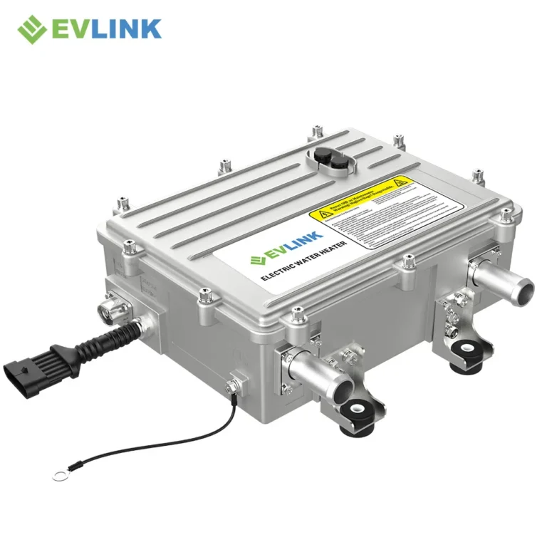
This article uses the HVH-R1402 liquid-cooled braking resistor as an example: its cold resistance at 25°C is 2.24 Ω, with a tolerance of ±10%; its operating voltage is 450–850 V DC; it can continuously output 140 kW for 20 minutes; its protection rating is IP6K9K; its operating temperature range is −40 to +85°C; and it is equipped with NTC temperature sensing and high-voltage interlocks.
All figures below are calculated directly from these input conditions.
Firstly, Rmin protects the chopper and should be checked at the high-voltage end
 When the braking chopper is turned on, the full bus voltage is applied across the resistor, with no other factors limiting the current. This is Schneider’s first rule and an absolute requirement that must not be breached: if the resistance falls below Rmin, the chopper’s IGBTs will be subjected to overcurrent and will be damaged. This is not a matter of derated operation, but of the device being directly destroyed.
Cressall’s guidelines also explicitly state that the minimum resistance value is specified by the chopper manufacturer. Therefore, the real question is never simply ‘how many ohms should be selected?’, but rather:
‘At the highest bus voltage, what resistance value will limit the current to within the chopper’s permissible range?’
When 850 V is applied to a 2.24 Ω resistor:
850 ÷ 2.24 ≈ 380A
This current must fall within the chopper’s safe operating range.
Most guides overlook tolerances. Our ±10% tolerance means that a product at the lower limit of the resistance range has a cold resistance of 2.016Ω. At 850V, the current will reach:
850 ÷ 2.016 ≈ 422 A
This is approximately 11 per cent higher than the nominal value.
Rmin must be checked under the most unfavourable conditions: the lowest resistance value within the tolerance range, combined with the highest busbar voltage. If 422 A meets the requirements, the fleet application will also meet them.
Secondly, Rmax ensures braking power and should be checked at the low-voltage end
Schneider’s second rule is that the resistance value must not exceed Rmax, where:
Rmax = Udc² ÷ Pmax
If the resistance exceeds Rmax, the device will not be damaged as a result; it simply cannot absorb the full peak power. This constitutes a reduction in capability rather than a failure.
The unique aspect of electric vehicle applications is that Udc is a range rather than a fixed value. As power is proportional to the square of the voltage, the power performance of the same resistor will vary significantly at the two ends of the voltage range.
Taking our 2.24 Ω product as an example:
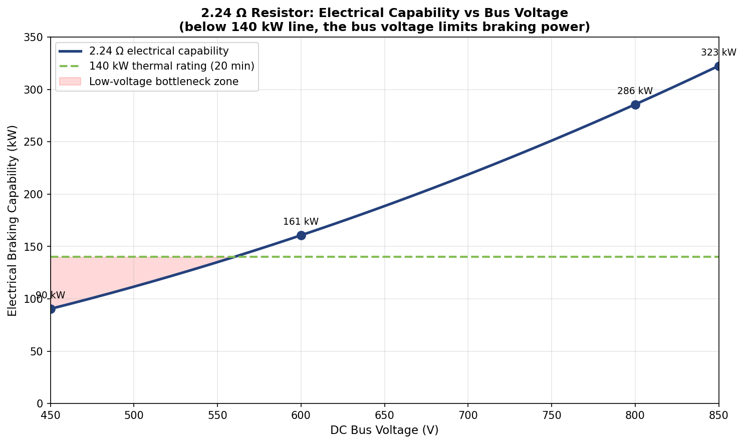
- High-voltage end: 850² ÷ 2.24 ≈ 323 kW
- Low-voltage end: 450² ÷ 2.24 ≈ 90 kW
For the same product model, the power dissipation at the low-voltage end is only approximately 28 per cent of that at the high-voltage end.
Consequently, Rmax must be verified at the lowest end of the voltage range; it cannot be assessed based on the nominal voltage alone. If a quotation request specifies an ‘800 V platform’, the first question to ask is what the minimum operating voltage is. This is the most commonly overlooked issue when selecting braking resistors for electric vehicles.
Tolerances also have an impact at this end of the range. For a product with a resistance of 2.464 Ω, the power at the minimum voltage of 450 V is:
450² ÷ 2.464 ≈ 82 kW
This is the combination with the lowest power capacity in the entire system; Rmax should be checked at this point.
Thirdly, the wider the voltage range, the narrower the range of selectable resistance values
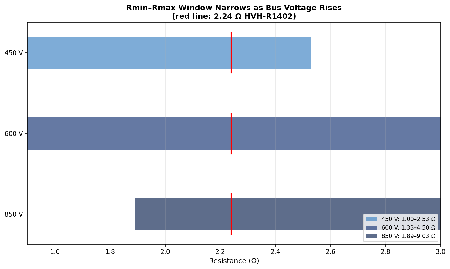
Our busbar voltage range is 450–850 V, with a ratio of 1.89 between the maximum and minimum voltages. As power is proportional to the square of the voltage, the power capacity of a single fixed resistance value varies by a factor of 3.57 across the entire voltage range.
Rmin is constrained by the upper limit of the bus voltage, whilst Rmax is constrained by the lower limit. The wider the voltage range, the narrower the acceptable range of resistance values between these two limits.
Taking a dual-platform application as an example, for the same 2.24 Ω resistor:
- On the 800 V platform: 800² ÷ 2.24 ≈ 286 kW
- On the 600 V platform: 600² ÷ 2.24 ≈ 161 kW
Each time the voltage platform is changed, the braking capacity must be revalidated for the lower voltage end.
All four boundary combinations must satisfy the Rmin–Rmax requirements: 422 A at 2.016 Ω/850 V, 82 kW at 2.464 Ω/450 V, and the nominal operating conditions in between.
When a customer enquires whether the same resistor model can cover both their 600 V and 800 V platforms, we will carry out these checks before providing an answer.
What this means for practical selection
Do not select the braking resistor value based on a single voltage value alone. Inverter selection tables are effective because their bus voltages are fixed, whereas your vehicle’s bus voltage is not fixed.
When checking Rmin, use the highest bus voltage and the lowest resistance value within the tolerance range; when checking Rmax, use the lowest bus voltage and the highest resistance value within the tolerance range. Only if both checks are passed will the resistor cover the entire operating range.
In terms of thermal performance, peak power determines the resistor value, whilst the duty cycle determines the rated power. Please refer to our accompanying article ‘Continuous Power versus Peak Power’. Basic calculation methods can be found in the ‘U²/P Resistor Value Calculation Guide’.
Please provide the following four pieces of data
In order to calculate the permissible resistor value range for your project, our engineers require:
- DC bus voltage range
Please provide the minimum and maximum voltages, not just the platform’s nominal voltage.
- Maximum current of the chopper or braking module
This value determines Rmin.
- Peak braking power requirement
This value determines Rmax and should be verified at the minimum bus voltage.
- Braking strategy under fully charged conditions
When the battery is fully charged and cannot accept regenerative braking charge, what proportion of the braking energy should the braking resistor absorb?
Once you have provided these four pieces of data, we will calculate the operating conditions at both ends of the voltage range and clearly state whether a single resistor model can cover all your platforms.
Frequently Asked Questions
Why does the same resistor have a power rating of 90 kW at 450 V but 323 kW at 850 V?
Because P = U²/R. Power is proportional to the square of the voltage; therefore, the 1.89-fold difference in voltage between 450 V and 850 V results in a 3.57-fold difference in power.
This is a law of physics, not a phenomenon specific to any particular product. All braking resistors adhere to this principle.
Can the same resistor be used for both 600V and 800V platforms?
Yes, but both terminals must be checked separately:
- Check Rmax using the minimum operating voltage of the 600V platform, as this is when the power capacity is at its lowest.
- Check Rmin using the maximum operating voltage of the 800V platform, as this is when the current is at its highest.
If both checks are passed, the same product model can be used for both platforms.
What happens if the resistance value exceeds Rmax?
The device will not be damaged as a result. However, when the chopper is fully conductive, the resistor cannot absorb the full peak power, resulting in reduced braking force.
Schneider Electric’s guidance documents classify this as a reduction in capability rather than a failure event. In terms of selection errors, this scenario is relatively safe, but it still indicates that the braking capacity has been undersized.
What happens if the resistance value is lower than Rmin?
When the chopper is turned on, the IGBT will be subjected to overcurrent, and the power device may be destroyed. This is an absolute red line that must not be crossed when selecting a braking resistor.
Unlike when the resistance exceeds Rmax, there is no gradual decline in performance in this scenario.
Is the cold-state resistance tolerance really important?
It is important, and both ends of the voltage range are affected.
Our ±10% tolerance means:
- At the high-voltage end, the current may be approximately 11% higher than the nominal value: 422 A at 850 V, rather than 380 A.
- At the low-voltage end, the power capacity may be approximately 9 per cent lower than the nominal value: 82 kW at 450 V, rather than 90 kW.
Both of these boundary operating conditions must satisfy the Rmin–Rmax requirements. Cold mornings cause the resistance value to shift towards the lower end of the tolerance range, and it is precisely under these conditions that current checks are most stringent.
Please provide us with the DC bus voltage range and the upper limit of the chopper current. We will calculate the values at both ends of the voltage range and clearly state whether the same resistor model can cover both of your platforms.
Find out more about our liquid-cooled braking resistors here: HVH-R1402, 2.24 Ω, DC 450–850 V, continuous power 140 kW.