Book Appointment Now


HVCH CAN Integration: An OEM Control Interface Checklist
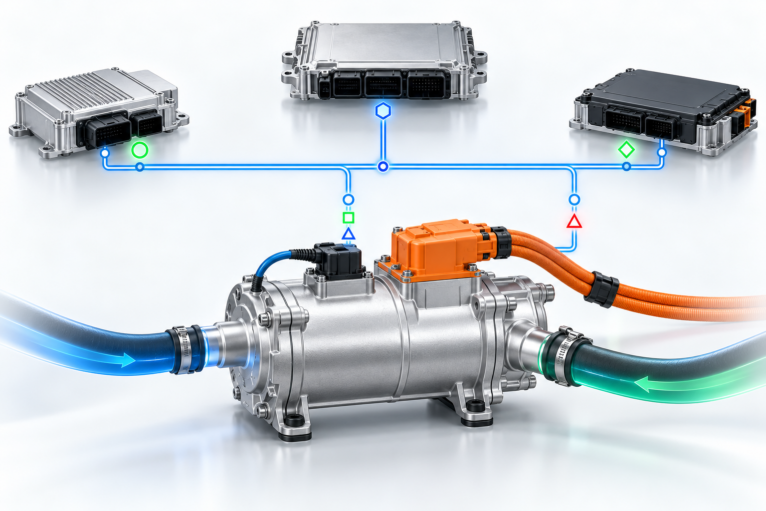
Engineering illustration of a generic high-voltage coolant heater connected to vehicle controllers over a CAN communication path.
The integration of the CAN bus for high-voltage coolant heaters (HVCH) should be regarded as a ‘vehicle control interface’ engineering task, rather than merely a simple wiring job.
Prior to software release, original equipment manufacturers (OEMs) and heater suppliers must reach a consensus on the following matters: command ownership, message timing, operating limits, diagnostic behaviour and safety failure protection states. Even if the electrical connection of the heater has been completed, inadequate definition of these interfaces may still lead to failure during vehicle-level debugging.
This checklist is intended to assist development teams working on electric lorries, buses and non-road mobile machinery in collating the information required for the integration of high-voltage coolant heaters. It is not a substitute for model-specific communication specifications. All signal names, scaling factors, timing and fault responses must be verified and confirmed in accordance with the selected heater model and the vehicle’s overall architecture.
First, clarify the control architecture
First, identify the controller responsible for issuing heating requests. Depending on the vehicle model, this command may originate from the Vehicle Control Unit (VCU), the thermal management controller, the Battery Management System (BMS) or the Heating, Ventilation and Air Conditioning (HVAC) controller. If there are multiple controllers capable of issuing heating requests, an arbitration mechanism must be defined, and the ultimate source of the command must be specified.
The architecture documentation should also cover the following: low-voltage power supply, wake-up strategies, CAN segments, terminating resistor configuration, high-voltage interlock paths (where applicable), coolant pump control, and devices capable of disabling heater operation. This prevents situations where it is only discovered during the later stages of debugging that the heater has been activated whilst the coolant pump or CAN network is not yet ready.
Confirming Command Signals with Suppliers
Vehicle development projects typically require a ‘heater enable’ command and a ‘target output’ request. The target output may be set to power, coolant outlet temperature or other model-specific setpoints. Command types or scaling factors from other heater series must not be adopted directly.
For each command, the Interface Control Document (ICD) should clearly specify the following information:
- CAN identifier (ID) and byte/bit positions;
- Data length, byte order (endianness), scaling factor, offset and valid range;
- Transmission cycle and timeout thresholds;
- Alive counter and checksum calculation methods (where applicable);
- Default values following wake-up or loss of communication;
- Conditions that cause a command to become invalid or be ignored.
Furthermore, it must be specified whether the controller is responsible for executing the requested ramp (i.e. smooth transition) control, or whether the heater itself manages the ramp. If both perform ramp control simultaneously, this may result in a heating rate slower than expected; if ramp control is entirely absent, this may cause undesirable transient fluctuations.
Status signals to be monitored by the vehicle
The heater should provide sufficient feedback to enable the vehicle to distinguish between ‘normal operating limits’ and ‘faults’. Specific signals vary by product, but the assessment should cover: operating status, actual or estimated output power, inlet and outlet temperatures (where supported), power supply status, communication status, and current diagnostic information.
A single ‘heater fault’ bit is generally insufficient for repair diagnostics. The vehicle must clearly identify the nature of the fault: whether it is transient, recoverable upon receipt of a valid command, recoverable after a power cycle (key cycle), or requires repair intervention to clear (locked state). It must be clearly defined what information is to be displayed to the driver, what is to be stored in the diagnostic log, and what countermeasures the thermal management controller should take.
Fault Handling and Degradation Strategies
Corresponding ‘safe states’ must be defined for situations such as loss of communication, invalid commands, low-voltage interruptions, abnormal coolant flow, overtemperature, insulation faults, high-voltage anomalies and unreasonable sensor data. It must not be assumed that all faults require the same response.
For example, in the event of a loss of communication, the heater may be required to cease operation after a set time-out period; in the event of a temporary output limitation, operation may continue with reduced demand; whereas for conditions that threaten hardware or electrical safety, an immediate shutdown and a controlled restart procedure may be required. Specific behaviour shall be determined by the technical specifications for each product model.
Coordinating CAN Bus Logic with Cooling Circuit Status
If the cooling circuit is not fully filled with coolant or has not been adequately vented, the heater software cannot self-correct. Before receiving an ‘enable’ command, the system strategy must verify that the cooling circuit meets the necessary conditions. Depending on the system architecture, this may involve: confirming the pump command, verifying coolant flow rate, or confirming that the temperature response is as expected.
During the commissioning phase, the heater’s command outputs, water pump commands, coolant inlet and outlet temperatures, high-voltage status and the heater’s own status should be recorded simultaneously. This data enables the differentiation between various issues, such as communication faults, insufficient flow, air locks (air entrapment) or thermal limitations. Before conducting independent diagnostics on the network, please ensure that the High-Voltage Heater (HVCH) installation checklist has been verified.
Network Timing and Bus Load Checks
Message timing should be set according to control requirements, rather than simply replicating the configurations of other electronic control units (ECUs). Commands that change frequently may require shorter cycles, whilst diagnostic data or identification information can utilise a slower update rate. Under various operating conditions—such as vehicle start-up, normal operation and sudden faults—the vehicle network must always maintain sufficient bus load margin. Test for delayed frames, dropped frames, invalid counters and complete communication failures. Verify that both the heater and the vehicle controller enter their intended states and complete recovery in the prescribed sequence.