Book Appointment Now


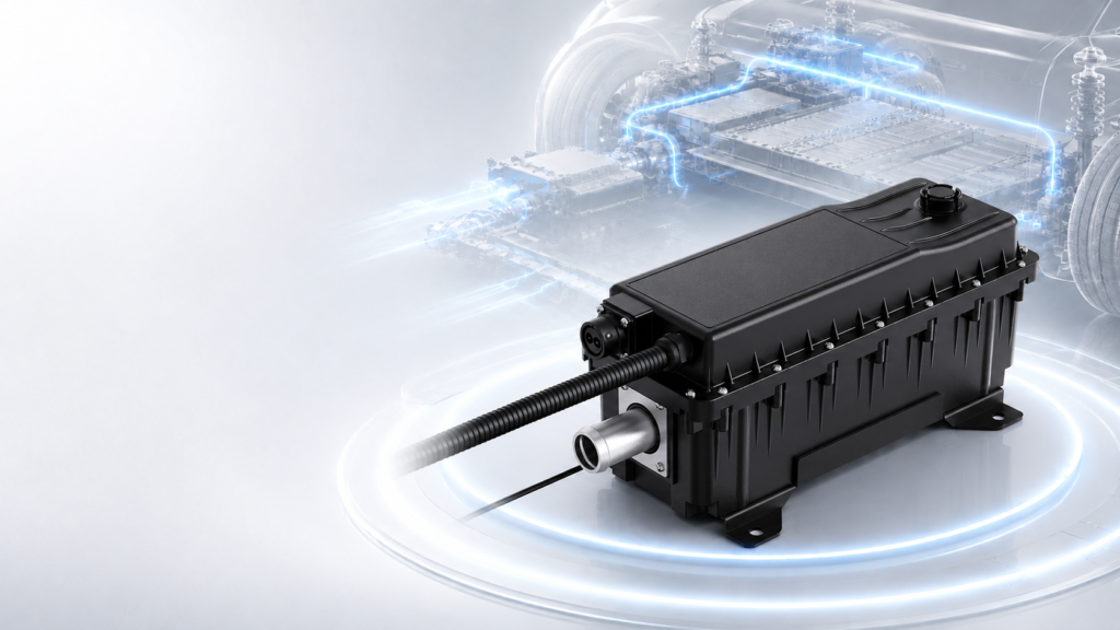
Before installing a high-voltage coolant heater, freeze the selected configuration, confirm the mechanical and coolant interfaces, and agree on the conditions required before the unit may be energized. A heater that fits inside the vehicle is not necessarily ready for operation: connector access, fluid routing, control permissions and commissioning evidence also need review.
This high-voltage coolant heater installation checklist helps OEM engineers and technical buyers organize that review. It is not a replacement for the selected heater’s installation manual or the vehicle manufacturer’s high-voltage safety procedures. Model-specific limits must be confirmed before work begins.
Identify the exact heater configuration, drawing revision, connector arrangement and software interface. Keep these together with the vehicle installation requirements. A product-family name or a nominal heating rating does not establish that two units have identical mounting points, connectors or operating permissions.
Review the EVLINK high-voltage coolant heater range, then request the documents applicable to the proposed configuration. Do not manufacture a bracket from a photograph or infer the pinout from a visually similar connector.
Assign an owner to each document and record any unresolved item. For example, an unknown connector withdrawal space is a packaging question to resolve before design release, not a dimension to estimate during assembly.
Review the heater in the installed vehicle coordinate system. Include the bracket, hoses, cables and neighboring equipment. Check whether technicians can engage the connectors, inspect their locking features and remove the unit using the approved service procedure.
Reserve room for the harness bend radius and connector withdrawal required by their specifications. Check hose routing through its expected operating movement, rather than only its position in an unloaded CAD model. Support the installation so that connected components do not impose unintended loads on the heater ports or connectors.
Installation position is configuration-specific. A supplier’s statement that one heater permits flexible mounting does not establish the permitted orientation of another model. Obtain the selected unit’s drawing and installation requirements before deciding port direction or bracket geometry.
For a commercial vehicle, document the environmental conditions at the proposed location: splash, contamination, nearby heat sources, vibration and service exposure. Ask for the applicable equipment limits and vehicle validation requirements. Do not use an enclosure rating alone as proof that every installation location is suitable.
Mark the flow direction, pump, heater, valves, heat exchangers and filling or venting provisions on the circuit drawing. Identify the operating states in which coolant actually passes through the heater. A pump command does not by itself prove flow through the selected branch.
Confirm coolant compatibility, concentration, operating pressure and temperature limits with the heater and vehicle suppliers. Treat these as documented inputs. Do not assume that all coolant formulations or mixtures are interchangeable, and do not borrow a concentration from a different vehicle program.
Ask how the installed circuit will be filled and air removed according to the approved procedure. Review potential air-retention locations and whether access remains available after surrounding equipment is fitted. The relevant question is whether the proposed installation supports the specified filling and venting process, not whether one generic venting method works for every heater.
Define how the team will verify circulation and leak tightness before heating is enabled. Use the selected equipment limits and the approved vehicle procedure; this checklist does not prescribe a universal pressure-test value, minimum flow or filling sequence. The HVCH flow and pressure-drop guide covers the separate task of matching the installed hydraulic circuit.
Review the high-voltage supply, low-voltage supply, communication connection and any protective interfaces separately. Identify the source of each signal and the conditions under which the heater can accept an operating request. Connector compatibility and application compatibility are different checks.
Confirm the selected unit’s electrical operating range against the vehicle supply conditions. Obtain the approved pinout, conductor and connector requirements, protective-device coordination and grounding or bonding instructions from the responsible design team. Do not choose a cable size, fuse or insulation-test setting from nominal heater power alone.
If the proposed unit includes an interlock interface, define its actual role and connection in the vehicle architecture. Do not assume every heater implements the same interlock arrangement. Likewise, obtain the agreed communication specification rather than treating a CAN or LIN label as a complete command definition.
Define who owns heating enable, the thermal target, inhibited operation and fault recovery. Establish how invalid inputs or loss of communication affect the unit and the vehicle. Those responses require project approval; automatically continuing the last heating request is not a universal fallback.
High-voltage commissioning belongs to personnel with the required training, equipment and authorization. UK HSE guidance on electric and hybrid vehicles describes electrical hazards, stored energy and the importance of competent personnel and manufacturer-specific information. This article is a planning checklist, not a live-work or isolation procedure.
Before the approved team enables heater operation, document which reviews must be complete and who releases each item. Include the mechanical installation, coolant readiness, electrical connections, control configuration and the applicable safety checks. Resolve discrepancies against the selected equipment instructions instead of bypassing a protection or forcing an enable request.
Do not release the installation solely because coolant temperature rises. Review the measurement location, accepted operating state, observed response and test conditions together. An apparently successful warm-up does not prove that all vehicle interfaces or abnormal-state responses meet the project requirements.
Create one installation record containing the drawing revision, unit identification, harness configuration, coolant specification, control-document revision and commissioning conditions. Attach inspection results and the relevant diagnostic or measurement logs.
Record deviations with an owner, disposition and retest requirement. A hose reroute, connector change or software update should trigger review of the affected checks. Avoid repeating an entire test campaign without reason, but do not assume that a previously accepted configuration covers a changed installation.
For purchasing, agree which documents accompany the proposed equipment and which interface decisions remain part of project engineering. The HVCH RFQ checklist helps place those requirements in the supplier discussion before order confirmation.
Only after checking the permitted positions for the exact configuration. Review the coolant routing, filling process, connector access and mechanical support together. Obtain confirmation where the released documents do not cover the proposed arrangement.
Not by itself. Check the actual rating, connection conditions and environmental limits alongside vehicle requirements for exposure and service. The suitability of the completed installation needs review, not just the enclosure label.
Request the applicable mounting drawing, orientation requirements, coolant and operating limits, connection drawings, control specification and commissioning instructions. Confirm availability and revision for the proposed configuration. This article intentionally does not assign universal numerical limits.
Prepare the vehicle type, proposed heater configuration, packaging drawing, coolant circuit, supply conditions and control architecture. Highlight unknown installation positions, service clearances or interface requirements that must be resolved before design release.
Send your HVCH installation brief to EVLINK to discuss the proposed arrangement and confirm the documentation available for that configuration. Use the agreed model-specific requirements as the basis for installation and acceptance.

Sizing a braking resistor comes down to three numbers. Get them right and the resistor disappears into the vehicle, doing its job for years. Get
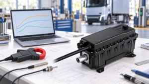
Verify HVCH power by separating requested output, electrical input and coolant-side heat transfer, with clear boundaries and project-specific acceptance criteria.
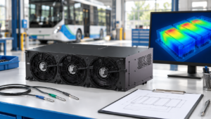
Separate measurement issues, coolant distribution and cooling capacity when investigating uneven battery temperatures in electric buses and trucks.
To make it easier for you to receive a quote, simply leave your information, and we will contact you as soon as possible.