Review BTMS condenser airflow, hot-air recirculation and vehicle-bay restrictions before freezing an electric bus or truck installation. Prepare the right evidence.
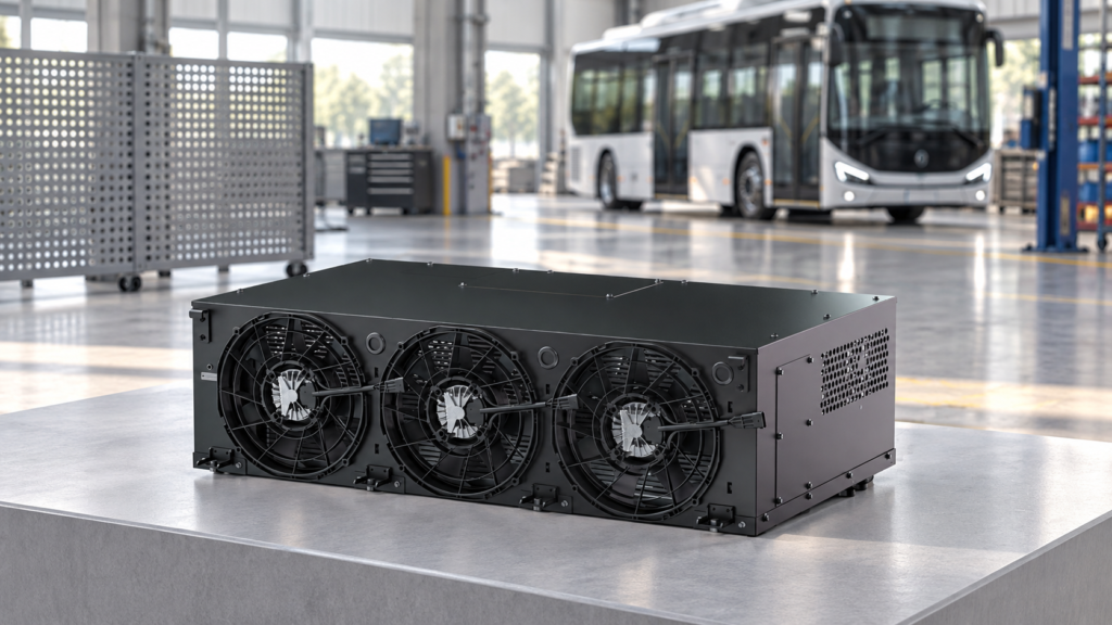
BTMS condenser airflow should be reviewed in the installed vehicle, not only around a unit on an open test stand. For an air-cooled battery chiller, an obstructed air path or warm discharge returning to the inlet can undermine cooling performance. Before selecting a larger unit, check whether the condenser is receiving the air conditions used for the supplier’s capacity rating.
This guide helps electric-bus and truck teams prepare an air-side installation review. It does not specify a universal clearance, airflow direction or fan setting. Those details must come from the selected unit’s released drawings and installation requirements.
Measure local inlet air, not just weather-station temperature
A vehicle ambient-temperature signal does not necessarily describe the air entering the condenser. A nearby heat source or discharge stream may change the local conditions. Identify the actual inlet and outlet from the supplier drawing before placing sensors; the visible fan face alone is not enough to establish direction.
For a development comparison, record outdoor reference air and several representative inlet locations together. Keep the reference sensor away from the unit’s discharge and direct heat sources, and document shielding and sensor placement. A repeatable inlet-to-reference difference is a reason to investigate the installation, not proof of a particular fault or a universal failure threshold.
Eaton’s chiller maintenance guidance identifies ventilation, clean condenser fins and prevention of hot-air recirculation as air-side concerns. Its product-specific distances and maintenance instructions are not EVLINK vehicle-installation specifications.
Review the complete path through the vehicle bay
Mark the intended intake, heat-exchanger path and discharge on the vehicle layout. Then review the installation with production panels, guards, wiring and nearby equipment in place. An open workshop arrangement cannot establish that the finished bay has an acceptable air path.
- Intake: check nearby panels, grille openings and areas where debris could accumulate.
- Discharge: identify where warm air can leave and whether it can return toward the intake.
- Added components: submit proposed ducts, filters or acoustic treatments to the supplier for pressure-loss and fan-operating-point review.
- Service access: retain the access needed for the approved inspection and cleaning procedure.
Do not copy a clearance from another chiller manual. YORK’s installation guidance illustrates why airflow restriction and recirculation matter, but its building-chiller dimensions and fan limitations apply to that equipment. Obtain the limits for your BTMS configuration instead.
Separate restriction from recirculation
Both can occur together, but they call for different evidence. A grille may restrict the air path without an obvious rise in inlet temperature. Recirculation may raise inlet temperature even when the opening looks generous. Fan command or sound alone does not establish the airflow through the installed heat exchanger.
Use a supplier-agreed comparison sequence. Hold the cooling request, coolant conditions and vehicle operating state as consistent as practical. Compare the intended production configuration with an approved development reference, then change one packaging variable at a time. Record differences in load, wind and initial temperatures rather than treating unlike runs as a controlled experiment.
A panel-open run may help isolate a packaging influence, but it is not a production acceptance result. Any alternative panel or duct arrangement must be structurally and electrically safe. Qualified personnel should follow released isolation and operating procedures; never remove guards near operating fans, expose energized equipment or bypass protection to continue a test.
Capture air-side and coolant-side evidence together
The following is a suggested development record, not a mandatory standard or a substitute for the supplier’s validation plan:
- Vehicle state: parked, charging or driving; relevant load, wind and panel configuration.
- Reference air and representative condenser-inlet temperatures, with sensor locations.
- Cooling request, fan command and available fan feedback; compressor state and reported faults.
- Coolant inlet/outlet temperatures and measured flow at a documented boundary.
- Time-aligned pack-temperature data, initial conditions and run duration.
These signals help avoid blaming air-side packaging for a coolant-distribution or control problem. Use the BTMS coolant-flow review for the liquid loop and the temperature-spread diagnosis guide when pack regions respond differently. Neither a single hot sensor nor a high fan request identifies the root cause on its own.
Agree the release evidence before freezing the layout
Send the supplier an annotated bay drawing, inlet/outlet identification, grille or duct details, nearby heat sources, installation photographs and the operating conditions to be covered. Ask for written confirmation of model-specific clearance, permitted added air-side resistance, service access and capacity-rating conditions. If these are not available, keep them as open engineering actions rather than filling the gap with generic numbers.
Include relevant stationary conditions in the agreed test plan, such as charging or waiting after a demanding route. A satisfactory moving-vehicle run does not establish that a different stationary state is covered. Acceptance should refer to the OEM’s battery limits and the supplier’s operating envelope, with the approved production panels fitted.
Questions to resolve with your BTMS supplier
Can a larger fan fix an airflow problem?
Not as an unreviewed substitution. Request an assessment of the complete air path and the proposed fan’s operating point, electrical demand, control compatibility and installation constraints. A larger nominal fan is not evidence that the condenser receives the required flow in the vehicle.
Should the grille or filter be removed permanently?
Do not use a diagnostic change as a production decision. Guards, filters and panels may serve other functions. Review their airflow effect together with protection, contamination, noise and service requirements, then validate the agreed arrangement.
What clearance should we specify?
Use the selected BTMS supplier’s released requirements and confirm them against the actual bay. There is no universal distance in this guide. Preserve access for approved maintenance as well as space for airflow.
Prepare an EVLINK installation review brief
When discussing your project with EVLINK, provide the vehicle-bay layout, intended cooling duty, local inlet-air conditions, coolant requirements and proposed grille or duct arrangement. This gives the engineering discussion a defined starting point before a configuration is selected.
Send your layout and operating conditions to EVLINK. Identify which dimensions and test conditions are confirmed and which remain open, so the review can focus on the decisions still needed.