Book Appointment Now


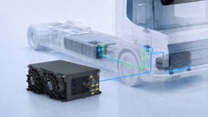
A BTMS quotation can look precise while its key input is still missing: how much heat the battery actually generates over the vehicle’s duty cycle. A single pack-capacity figure or “peak charging power” cannot answer that question. For an electric bus or truck, you need a heat-load profile, the conditions at which cooling is required, and the battery maker’s temperature limits. This worksheet shows how to assemble that brief before selecting hardware or comparing supplier ratings.
Battery heat generation is not the same as rated BTMS cooling capacity. The first describes heat produced within the cells, electrical connections and pack under a specified operating condition. The second describes heat the thermal system can remove at a stated coolant and ambient condition. The two become comparable only after you define the system boundary and account for other loads in the coolant circuit.
In NREL’s battery thermal characterization report, heat generation measurements were obtained across different power profiles and temperatures. Do not use a universal percentage of electrical power as a substitute for pack-specific data. Cell chemistry, state of charge, temperature, current and pack design can change the answer.
Ask the battery or vehicle engineering team for the following, with units and test conditions attached:
EVLINK’s BTMS FAQ similarly requests battery, temperature, heat-generation and coolant information when assessing an application. If a supplier is given only battery capacity, the resulting BTMS size is a preliminary assumption, not a validated selection.
Create rows for the operating cases that could govern hardware selection: a sustained climb at high ambient temperature, stop-start urban service, depot or opportunity charging, and recovery after a cold soak. For each time step, enter pack heat generation in kW from an OEM-approved model or measurement. Add only heat entering the chosen coolant-loop boundary that is not already included in the pack figure—for example, a separately characterized power-electronics branch. Do not count interconnect losses twice if the pack measurement already includes them.
| Operating case | Duration | Pack heat input | Other loop loads | Starting pack / ambient temperature | Coolant target and flow | Temperature-limit result |
|---|---|---|---|---|---|---|
| Hot-day route | Enter tested profile | OEM data, kW versus time | Documented only | Record both | Record range | Pass / investigate |
| Charging session | Enter charging profile | OEM data, kW versus time | Documented only | Record both | Record range | Pass / investigate |
| Cold-start recovery | Enter preparation window | OEM heating/cooling requirement | Documented only | Record both | Record range | Pass / investigate |
For a consistently defined loop boundary, the basic bookkeeping expression is:
Required heat removal at time t = pack heat entering the loop + other verified loop loads + environmental gains − any heat temporarily stored in the pack/loop.
The storage term is why a short heat-generation spike does not automatically dictate the same continuous chiller rating. Its use needs a transient thermal model and a battery-temperature check; it is not a free sizing discount. Conversely, an extended load can exhaust that buffer. A DOE vehicle thermal-management study distinguishes transient peaks from continuous cooling requirements by considering their duration.
Report at least three outputs for each case: maximum instantaneous load, highest sustained load over the relevant control period, and total thermal energy over the event in kWh. Include the pack starting temperature and the maximum predicted cell temperature. A 10-minute charging event and a two-hour grade may point to different design constraints even when one has the higher peak kW. DOE research on extreme fast charging illustrates why charging heat must be evaluated as its own scenario rather than inferred from driving alone.
For illustration only, imagine an OEM measures 7 kW of pack heat during a defined continuous segment and separately validates 1 kW from another component entering the same loop. That boundary has an 8 kW heat input in that segment. This is not an EVLINK performance claim or a recommended product size. The actual BTMS must still be checked against its capacity map at the specified coolant and ambient conditions, as well as control, pressure-drop and packaging limits.
When the coolant is well mixed and the flow and temperature measurements represent the same steady-state boundary, removed heat can be estimated as Q = mass flow × specific heat × coolant temperature rise. Convert flow to mass per second, use the actual coolant mixture’s properties at the operating temperature, and record sensor locations. This calculation checks measured loop heat transfer; it does not reveal the battery’s internal heat generation by itself.
At very low flow, during valve transitions, or with large temperature gradients, a quick inlet–outlet calculation can mislead. Record uncertainty and repeat the measurement under stable conditions. A pressure-drop measurement belongs beside the flow result because a pump may not deliver its nominal flow once installed in the full circuit.
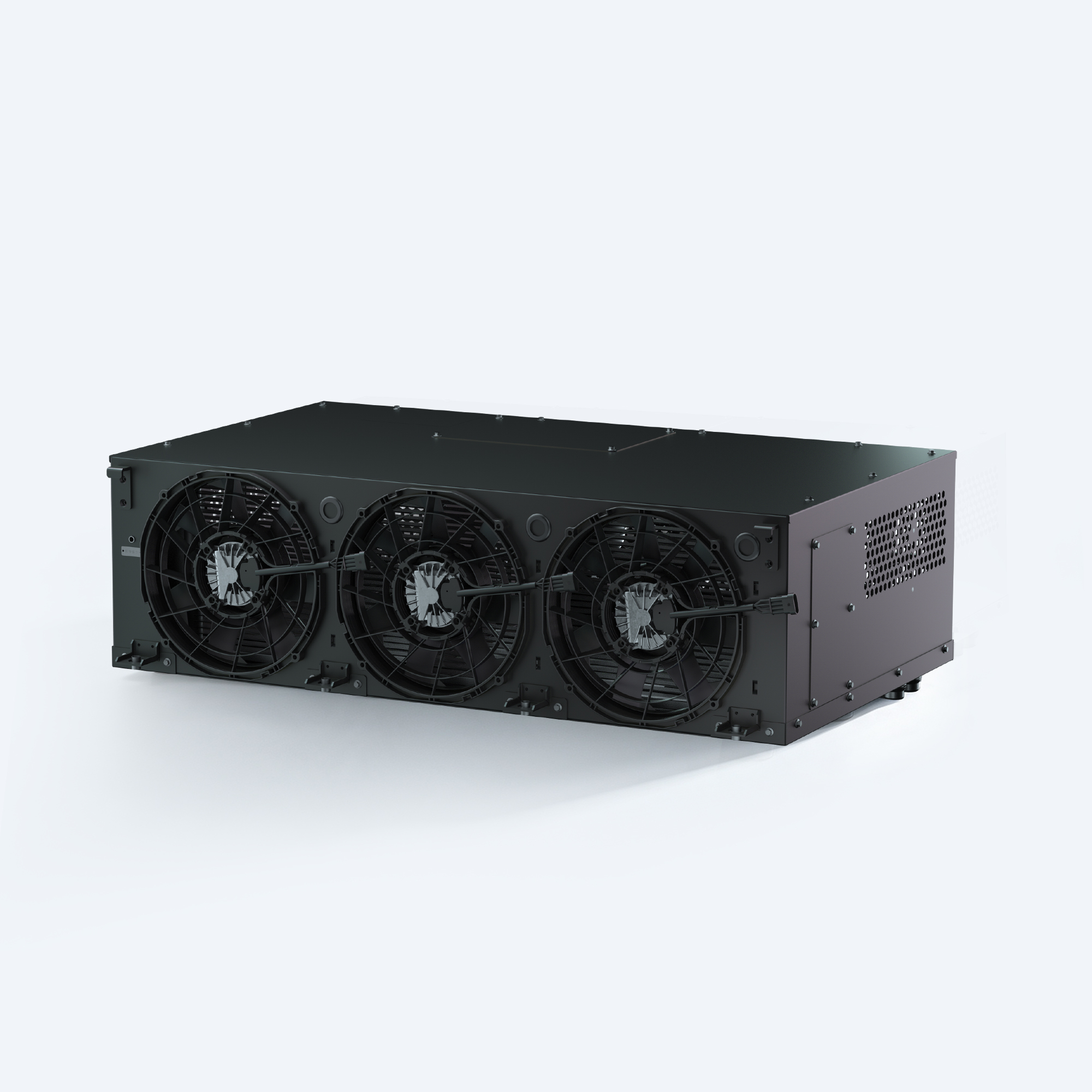
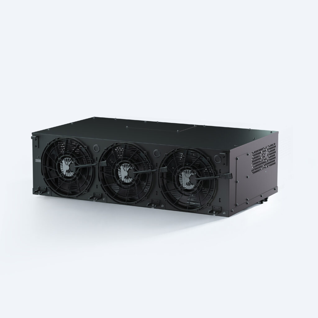
A catalog label such as “5 kW BTMS” is a useful shortlist marker, not proof that 5 kW is available in your vehicle at every ambient temperature. Ask for the supplier’s test conditions and capacity map: ambient temperature, coolant inlet/outlet temperatures, flow, voltage and control mode. Then compare the achievable capacity with each duty-cycle case, not only with one headline heat-load value. EVLINK’s 5 kW BTMS product page is a model overview; engineering selection still requires application data.
Check the interface as well as the thermal number. A unit that can remove the heat in a laboratory may be unsuitable if the vehicle cannot supply its electrical power, the coolant pump cannot meet the pressure-drop requirement, or the controls cannot coordinate with the battery-management system. The separate commercial-EV BTMS selection guide covers these broader integration questions.
Send suppliers one controlled version of the duty-cycle data and ask them to respond against the same scenarios. Include: the defined loop boundary, a heat-load curve or table, event duration, allowable battery-temperature range, coolant specification, inlet-temperature targets, ambient range, voltage, packaging envelope and required control signals. Request performance at the boundary conditions rather than a single nominal kW value.
For validation, specify what the test must prove: stable temperature during sustained operation, recovery time after a transient event, charging readiness, pump/flow behavior, power draw and fault response. Keep this procurement brief linked to the later BTMS validation checklist so the selected system can be tested against the same assumptions that justified its size.
No. Capacity describes stored energy, not the rate of heat generation during a route or charge. Obtain pack-specific heat-generation data or a validated model tied to current, state of charge and temperature.
Not necessarily. Check the spike’s duration, usable thermal storage, cell-temperature limit and recovery time with a transient model. The continuous requirement may govern instead. Never ignore a peak simply because it is short.
No. Current direction, rate, pack temperature and control objectives differ. Evaluate charging as a separate case, especially if the vehicle must accept power soon after a cold start or route.
Request an approved heat-load envelope or anonymized time-series covering the intended operating cases, with the measurement boundary and uncertainty stated. A preliminary quote can proceed on assumptions, but final sizing needs approved inputs.
No. More nominal capacity may increase size, cost and electrical demand without fixing flow, controls or capacity loss at the actual duty point. Compare complete system behavior against battery limits.
If you are specifying BTMS hardware for an electric bus or truck, send EVLINK your approved heat-load envelope, route and charging cases, coolant details, battery-temperature limits and packaging constraints. Our team can review which product family and interface questions deserve detailed engineering discussion. If some inputs are still unknown, identify them explicitly so a preliminary proposal is not mistaken for a validated design.

Sizing a braking resistor comes down to three numbers. Get them right and the resistor disappears into the vehicle, doing its job for years. Get
Verify HVCH power by separating requested output, electrical input and coolant-side heat transfer, with clear boundaries and project-specific acceptance criteria.
Separate measurement issues, coolant distribution and cooling capacity when investigating uneven battery temperatures in electric buses and trucks.