Book Appointment Now


The electric bus thermal management market is on track to grow from about $3.2 billion in 2025 to $8.7 billion by 2034, an 11.8% annual growth rate, according to Dataintelo. Compressors alone account for nearly 29% of component value, heat exchangers 24%, and HVAC controllers over 21%. As volumes scale, cost pressure moves from individual components to system architecture: how many controllers, how much wiring, how many validation campaigns.
One of the clearest architectural answers is consolidation — combining the electric compressor controller, the refrigeration system ECU, and the high-voltage PTC controller into a single integrated thermal management controller. Everyone agrees integration “saves cost.” Fewer people can show the math. This article does exactly that: where the money goes in a conventional three-controller architecture, and what a 3-in-1 design removes, line by line.
A typical electric bus thermal system needs three control functions, and conventionally each gets its own box:
Three boxes, three part numbers, potentially three suppliers. Each controller, taken alone, is a reasonable piece of engineering. The cost problem is not in any single controller — it is in the multiplication by three. Every controller brings its own housing, its own PCB, its own connector set, its own low-voltage supply input, its own CAN node on the vehicle network, and its own calibration and validation campaign. None of these items is dramatic on its own. Together, tripled across the system, they are.
To see the real cost structure, it helps to split it into five buckets. The controller purchase price is only the first.
1. Controller hardware, times three. Housings, PCBs, connectors, power stages. Three sets of mechanical parts, three sets of electronics manufacturing, three incoming-inspection routines. Even before a single line of software, the mechanical and electrical duplication is real money.
2. Wiring harness. High-voltage feeds, low-voltage supplies, CAN branches — copper, weight, and connectors. Every interface between boxes is a connector pair, and every connector pair is both a cost item and a potential failure point. Harness cost scales with the number of boxes, not just the length of wire.
3. Installation labor. Three mounting operations on the vehicle, three wiring jobs, three commissioning and end-of-line test steps. On a production line running hundreds of buses a year, the labor delta between installing one controller and three is straightforward arithmetic.
4. Validation cost. Design verification, production validation, and EMC testing — per controller. Three separate units mean three EMC campaigns, three environmental test programs, three sets of documentation for type approval. Validation is often underestimated because it sits in engineering budgets rather than the BOM, but it is paid for on every platform.
5. Warranty cost. More interfaces mean more failure points: connectors corrode, harnesses chafe, CAN nodes drop out. Field failures, diagnostic time, and replacement parts scale with system complexity, not with any single component’s quality.
Third-party evidence supports the direction, if not the exact number for thermal controllers. IDTechEx’s analysis of integrated power electronics found integration saving up to 25% versus discrete designs, through shared housings, passive components, copper, control circuitry, and cooling — we cite this as an analogy from power electronics, not as a measured figure for thermal controllers. Integration case studies from suppliers like INFAC and Vicor list the same benefit categories: fewer high-voltage cables and connectors, less cooling redundancy, fewer brackets and housings, lower BOM count, fewer leak points, simpler harness routing, and better manufacturing consistency. ResearchAndMarkets’ NEV thermal management outlook makes the point directly for our domain: integrating discrete drivers for the expansion valve, water pump, and water valves into the thermal management controller reduces system cost and significantly lowers component ECU failure rates.
Now the other side of the ledger. A three-in-one thermal management controller — compressor controller, refrigeration ECU, and HV PTC controller in one unit — removes the ×3 duplication bucket by bucket:
There is also a control-architecture dividend that is harder to put a number on but easy to explain: the three control loops — compressor speed, expansion valve opening, and fan speed — run inside one unit, sharing sensor data with no inter-controller communication delay. We explain how those loops coordinate in our companion piece on EV thermal management control strategy.
Cost discussions usually stop at the BOM. They shouldn’t. Reliability improvements from integration show up in warranty reserves, service costs, and fleet uptime:
The most common objection to integration is loss of flexibility: “If I consolidate, am I locked into your choices?” For this controller architecture, the answer is no — and the specifics matter:
In short: what gets standardized is the duplicated infrastructure — housings, supplies, network nodes, cooling. What stays flexible is everything project-specific.
If you are comparing integrated thermal controllers for a bus or commercial-vehicle platform, here is the checklist we recommend walking through with any supplier:
Catalog comparisons only go so far. The right controller depends on your vehicle platform, voltage architecture, compressor choice, and operating climate. Share your vehicle type, platform voltage, and compressor parameters, and we will recommend a controller configuration with honest trade-offs — including telling you when integration is not the right answer for your project.

Sizing a braking resistor comes down to three numbers. Get them right and the resistor disappears into the vehicle, doing its job for years. Get
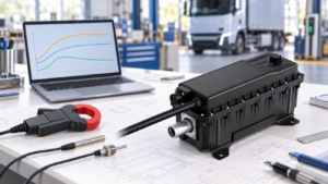
Verify HVCH power by separating requested output, electrical input and coolant-side heat transfer, with clear boundaries and project-specific acceptance criteria.
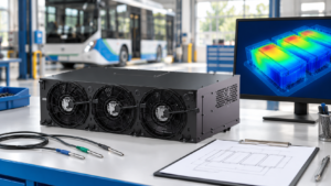
Separate measurement issues, coolant distribution and cooling capacity when investigating uneven battery temperatures in electric buses and trucks.
To make it easier for you to receive a quote, simply leave your information, and we will contact you as soon as possible.