Book Appointment Now


A battery thermal management system can report a reasonable coolant temperature while part of the battery is still outside its approved operating conditions. Before choosing temperature sensors or tuning the BTMS, define what each measurement represents, where it is taken and how it will be checked against the battery requirements.
This guide helps electric bus and truck OEM teams review coolant and battery temperature measurements. It does not prescribe a universal sensor count, mounting position or temperature limit. Those decisions belong to the battery design, coolant architecture and project validation plan.
Start with the decision, not the sensor connector. A controller regulating coolant delivery needs different evidence from a BMS deciding whether the battery may charge. A surface probe, a fluid probe and a temperature estimated by a model are not interchangeable signals.
Research on sensor placement for battery temperature estimation treats the spatial temperature field as a problem that cannot be reduced to an arbitrary measurement location. For your vehicle, the useful question is which conditions the installed measurements can detect—and which conditions still need validation measurements or a justified model.
Give these values distinct names in drawings, software and logs. “Battery temperature” is too ambiguous if one supplier means a BMS cell-surface measurement and another means the coolant returning from the pack.
Draw the installed coolant path, including the BTMS, battery branches, valves, bypasses and any other heat exchanger. Mark the direction of flow for each operating mode. A label such as “inlet” is meaningful only when it names the component: the BTMS inlet is not the battery inlet.
As a project review method, assign a unique identifier to each measurement point and place it on the schematic before freezing the harness. Record the measured medium, the physical location, the controller receiving the signal and the action that uses it. Identify whether a displayed value is measured, calculated or copied from another controller.
A reading before the battery describes delivered coolant. A reading after one battery branch describes that branch’s return. A reading after several returns merge describes the mixed stream. It cannot reveal every branch independently.
This matters on vehicles with distributed packs. One return value may conceal a branch that receives less coolant than intended. If branch distribution is a release requirement, establish how it will be measured during validation rather than assuming the common return proves uniform operation. Pair this review with the BTMS flow-rate and installed-loop checks.
For each point, keep a short record containing:
This record is an engineering handover tool, not a claim that an EVLINK unit contains every sensor listed. Confirm the actual supplied measurements for the proposed BTMS configuration.
A precise sensing element can still give an unrepresentative installed reading. The sensor assembly, thermal contact, surrounding material and exposure to the measured medium all affect the result. MCNICSENSOR’s placement guidance explains why mechanical contact and the thermal path need to be considered alongside the electrical characteristics.
For a fluid probe, review the approved insertion arrangement, sealing, materials and local flow conditions. For a surface measurement, review attachment and insulation with the component supplier. Do not drill a battery enclosure, replace a wetted sensor or change mounting torque using generic advice from an article.
Request response information under stated conditions. A response measured in one test medium may not describe the installed assembly during a vehicle transient. Consider both the probe’s response and the time required for a change upstream to reach the sensing point.
The practical review should also cover service. Can the sensor be replaced without disturbing an approved attachment? Is the correct part identifiable? Could two similar connectors be interchanged? Include the measurement-point identifier in service information so a plausible reading is not accepted from the wrong location.
During a sufficiently steady cooling condition, an inlet-to-outlet difference can help interpret the loop. But a small difference does not by itself establish that every battery region is cool enough. A large difference does not by itself identify a defective BTMS. Flow, heat input, measurement positions, branch mixing and timing must be considered together.
In a transient, avoid subtracting an upstream value at one moment from a delayed downstream response and calling the result a simultaneous battery condition. Log measurements on a common timeline, document the sampling behavior and identify intervals that are appropriate for comparison.
For example, consider two battery branches merging into one return. If their outlet conditions differ, the downstream sensor sees the combined stream. That illustrative arrangement shows why a common return is useful for system monitoring but insufficient to diagnose which branch needs attention. It is not a report of an EVLINK customer test.
The battery supplier’s approved measurements and limits remain the basis for judging battery readiness. Coolant delivery is one part of the evidence, not a substitute for the pack’s acceptance criteria.
For a bus preparing for its first departure or a truck returning to a charger, check how the measurements behave through the transition—not only once temperatures stabilize. Define the starting condition, available preparation time and battery operating limits before the test.
Use an approved, independently checked reference measurement where needed. Record its location and uncertainty. Comparing two channels attached at different places is not a calibration check: it combines instrument error with real thermal differences.
The exact fault-detection timing and fallback belong to the project risk assessment and control specification. This measurement review does not define a universal safe-state policy. Coordinate it with the BMS, VCU and BTMS interface contract.
A useful release record shows more than a temperature plot. It identifies the sensing locations, equipment versions, reference instruments, test conditions and the acceptance requirement each trace addresses. It also names the limitations: an uninstrumented branch or untested duty should not quietly become an assumed pass.
Ask the battery and thermal-system teams to agree on what will demonstrate acceptable coolant delivery, battery condition and abnormal-input behavior. Keep failed cases and retest results with the BTMS validation plan. Successful decoding or a stable dashboard value is not sufficient physical verification.
Not automatically. It represents the fluid at its measurement point. Using it to estimate a battery condition requires a validated relationship and approval for the intended control decision. It does not directly measure every cell or an internal hot spot.
No. Sensor coverage depends on pack construction, branch layout, control strategy and the validation evidence. Ask which thermal conditions must be detected and how the proposed coverage demonstrates them, rather than buying a universal sensor count.
They may be measuring different locations, media or moments in the thermal response. Check identification, calibration, contact and timing before concluding that either sensor is faulty. Document the expected physical difference under the test condition.
Provide your coolant schematic, pack arrangement, battery supplier’s thermal requirements and available temperature-channel list. Include the cold-start or charging condition that concerns you, with time-aligned logs if available. Remove confidential information that is not needed for the discussion.
Discuss your BTMS measurement and integration requirements with EVLINK. Confirm the supplied sensor locations, interface documents and project validation responsibilities for the specific configuration before commissioning.

Sizing a braking resistor comes down to three numbers. Get them right and the resistor disappears into the vehicle, doing its job for years. Get
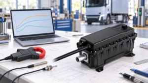
Verify HVCH power by separating requested output, electrical input and coolant-side heat transfer, with clear boundaries and project-specific acceptance criteria.
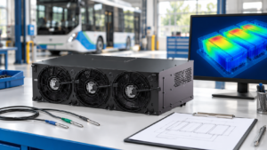
Separate measurement issues, coolant distribution and cooling capacity when investigating uneven battery temperatures in electric buses and trucks.
To make it easier for you to receive a quote, simply leave your information, and we will contact you as soon as possible.