Book Appointment Now


To integrate a battery thermal management system (BTMS) with the battery management system (BMS) and vehicle control unit (VCU), agree on control ownership, signal definitions and abnormal-state behavior before commissioning. A CAN connection that carries messages is only the starting point. Your electric bus or truck must also interpret those messages correctly, act on the right request and report what the equipment is actually doing.
This guide gives OEM engineers and technical buyers a practical interface review and acceptance checklist. The exact CAN identifiers, protocol, temperature limits and timing values must come from the selected equipment and vehicle specifications.
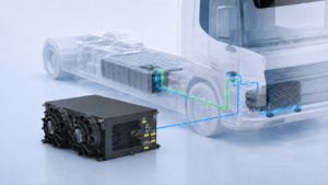
Start with a functional diagram showing the BMS, VCU, thermal controller and the equipment each controller commands. The diagram should answer a simple question: who has authority over each operating decision?
The BMS monitors battery conditions and exchanges information with other vehicle systems. MPS describes BMS communication with the VCU and thermal system, including temperature and battery-state information. That general architecture does not specify which controller owns your particular coolant setpoint or operating mode.
For each command, identify the request source, the controller that accepts or rejects it, and any local protection that can override it. A thermal request might pass through the VCU, or a thermal controller might use approved BMS inputs directly. Confirm the actual arrangement with all three suppliers.
Do not let two controllers independently change the same setpoint without an agreed arbitration rule. Resolve that responsibility during BTMS system selection, before the harness and software interfaces are frozen.
A signal list says what can be transmitted. An interface contract also says when a value is usable, what action it permits, and how the receiving controller responds when it is missing or invalid.
Request the network specification, the applicable DBC or equivalent protocol document, the connector pinout and the firmware revision together. Confirm Classic CAN or CAN FD as applicable, bus parameters, identifier format, message ownership and any gateway routing. A shared CAN connector does not establish application compatibility.
For conventional high-speed CAN, check the physical network against its specified wiring and termination plan. Kvaser’s error-frame guidance identifies termination and matching bus parameters as checks when communication fails. Avoid adding a terminator to every device: first establish where the network ends and whether equipment already includes termination.
If a supplier describes an interface as J1939, obtain the actual supported messages, addressing rules and project mapping. Do the same for a proprietary CAN interface. Neither label tells you that the vehicle and BTMS agree on every command, state or diagnostic meaning.
Use the following groups as an interface-review starting point. They are candidate requirements, not a claim that every BTMS exposes every signal.
For every implemented signal, record its sender, receiver, unit, range, encoding and update behavior. Also document startup values, unavailable-data codes and the conditions under which the receiver may use it.
A DBC file describes how CAN data maps to physical values, including bit position, byte order, signedness, scale and offset. Check those definitions with the actual software versions. The separate interface requirements should specify behavior that a decoding file alone does not settle.
A decoded temperature can look reasonable while representing the wrong measurement location. Label battery temperature, coolant inlet temperature and coolant outlet temperature distinctly. The coolant measurement cannot by itself establish that every cell meets the battery supplier’s acceptance limits.
Likewise, a commanded pump speed is not a measured coolant flow. Relate the available feedback to the installed-loop flow and pressure-drop checks. If no flow sensor is present, document how flow will be verified during commissioning rather than naming a command field “actual flow.”
Define how the receiver recognizes stale or invalid data. Agree on the timing requirements and any freshness mechanism used by the selected protocol. Do not choose a universal timeout from an unrelated vehicle; it must fit the message cycle, system response and approved fault policy.
Write the expected sequence from sleep to ready, then from ready to active heating or cooling. Include the order in which controllers wake, when their inputs become valid, when electrical power is available and when an enable request may be accepted.
For a cold-climate bus or truck, test the transition from overnight parking to depot preconditioning and departure. Establish what happens if the vehicle wakes while the thermal unit is still initializing, or if a charging connection is removed during preparation.
The control specification should also distinguish a request to begin heating from permission to charge the battery. Battery charging limits must follow the approved battery requirements. Define these operating assumptions alongside the cold-weather preconditioning brief.
During shutdown, specify which functions stop immediately and whether any equipment requires a controlled stop or continued circulation. Use the selected equipment instructions and the vehicle’s risk assessment; do not assume one shutdown sequence suits every heater, compressor and coolant circuit.
Review missing messages, invalid inputs, controller resets, rejected commands and equipment faults separately. “Communication fault” is too broad to tell a service engineer which input was lost or why a thermal request was inhibited.
For each condition, document detection, local unit response, vehicle response, diagnostic reporting and recovery. A communication failure should lead to the behavior approved for that operating state. Continuing the last command, disabling an actuator or maintaining a limited function are design decisions requiring system-level review; this article does not prescribe a universal safe fallback.
Specify whether recovery is automatic or requires a new valid command, reset or service action. Test it explicitly. A unit that restarts when traffic returns may still need the vehicle to re-establish permissions and operating state.
Maintain a clear boundary between thermal control and battery protection. Successful CAN integration is not evidence of functional-safety certification, nor does it replace the battery and vehicle suppliers’ protection requirements.
Use an approved test setup and procedures appropriate to the equipment and high-voltage system. Carry out simulated communication tests before exposing a vehicle or battery to uncontrolled operating conditions.
Agree on the expected outcome for each test case before collecting results. A log showing frames on the bus is insufficient: the receiving controller must interpret the intended value, select the expected state and produce the required response within the approved conditions.
Keep the raw log, decoding revision and measured response together. Your BTMS validation plan should identify unresolved failures, retest evidence and who accepts the interface for the next project stage.
Before placing an order, ask which interface documents are available for the proposed configuration and which require project engineering work. Include the DBC or protocol specification, connector drawing, operating-state definition, diagnostic list, firmware identification and change-control process in the technical discussion.
Ask how an interface change will be communicated and validated. Changes to message timing, units, invalid codes or startup behavior can affect the vehicle even when the enclosure and cooling capacity remain the same.
For procurement, the useful comparison is the completeness and compatibility of the proposed interface, supported by documents and test evidence. A broad “CAN supported” statement should lead to a technical review rather than end it.
Either arrangement may be used, depending on the vehicle architecture and equipment interface. Define the actual command path and authority with the battery, vehicle and thermal-system suppliers. A direct connection still needs agreed signal meaning, permissions and fault behavior.
No. It supports message decoding and encoding, but commissioning also needs operating-state requirements, timing and validity rules, wiring information, diagnostics and acceptance tests. Match the DBC revision to the installed controller software.
Use a project-approved requirement based on the message cycle, receiver behavior and system risk assessment. The detection time and fallback response should be defined and tested together. There is no single value suitable for all BTMS applications.
Review the EVLINK battery thermal management system range before submitting your interface brief. Identify the proposed configuration, then confirm its available control interface and project documentation with EVLINK.
For a project discussion, provide your vehicle type, battery supplier’s approved thermal requirements, operating duty, control architecture and available network documentation. Identify the proposed BTMS configuration and the commands, feedback and diagnostic behavior you need.
Send your BTMS integration brief to EVLINK to discuss the required interface and confirm the documents available for the proposed configuration. Final message mapping and operating behavior should be agreed for that specific vehicle project before commissioning.

Sizing a braking resistor comes down to three numbers. Get them right and the resistor disappears into the vehicle, doing its job for years. Get
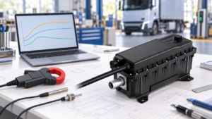
Verify HVCH power by separating requested output, electrical input and coolant-side heat transfer, with clear boundaries and project-specific acceptance criteria.
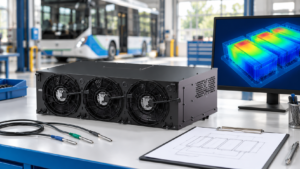
Separate measurement issues, coolant distribution and cooling capacity when investigating uneven battery temperatures in electric buses and trucks.
To make it easier for you to receive a quote, simply leave your information, and we will contact you as soon as possible.