Book Appointment Now


When the battery is fully charged, where does the energy generated by regenerative braking go?
If you ask, “When the battery is fully charged, where does the energy generated by regenerative braking go?” most people tend to give just one answer: it’s taken over by the friction braking system. For a passenger car traveling downhill for 90 seconds, this explanation is acceptable; but for a fully loaded truck at the start of a 20-minute downhill stretch, that’s when the real problem begins.
Energy doesn’t simply vanish into thin air just because the battery can’t accept it. During the descent, regardless of whether the battery pack needs it, the truck is constantly converting potential energy from elevation into electrical energy. Every kilowatt of energy ultimately goes somewhere: either into the battery, converted into heat on the brake rotors, or dissipated through resistors. For heavy-duty vehicles, this “third option” must be specifically engineered and equipped with an appropriate cooling system. If left unchecked, by the end of the descent, the vehicle is likely to experience a decline in braking performance—or “brake fade”—due to overheated brakes.
Batteries refuse to accept energy more often than you might think
There are three common operating conditions that limit a battery pack’s ability to accept a charge.
The first is a high state of charge (SOC). When the battery is nearly full, the battery management system (BMS) significantly reduces the charging current to protect the cells; when the charge level reaches 100%, the battery is effectively unable to accept any more energy. The regenerative braking curves in technical specifications are typically plotted based on the battery pack being at about half charge. If a vehicle begins descending a hill after being fully charged, its performance will differ significantly from what is described in the specifications.
The second factor is low-temperature environments. In severe winter conditions, the battery pack’s ability to accept a charge is only a fraction of what it is at normal temperatures; therefore, even with a charge level of just 60%, regenerative braking performance on a cold morning will be significantly reduced.
The third factor is the downhill descent itself: a truck that begins a descent with an 85% charge is likely to reach the charging limit set by the BMS during the descent, as the downhill motion itself continuously “recharges” the battery pack. Regenerative braking capacity may already be diminished before the descent is complete; under extreme road conditions, these three factors may even occur simultaneously.
Before blaming the braking system, let’s do the energy math for the descent.
Take a fully loaded truck with a gross vehicle weight of 60 metric tons as an example, assuming a vertical descent of 300 meters. Potential energy alone amounts to approximately 177 megajoules (MJ), or about 49 kilowatt-hours (kWh). Even after accounting for various losses, the electric motor will still supply approximately 40 kWh of electrical energy to the DC bus during this descent. Over the 20-minute descent, this means an average continuous load well exceeding 100 kilowatts, sustained without interruption throughout the entire descent. This energy must be accounted for on the battery side. If the battery pack is already fully charged, too cold, or both at the start of charging, its capacity to absorb those 40 kilowatt-hours (kWh) of energy is virtually zero. However, the total energy does not decrease as a result. The energy that the battery pack cannot accept must be absorbed by other systems on the vehicle within the same 20-minute period and at the same power level.
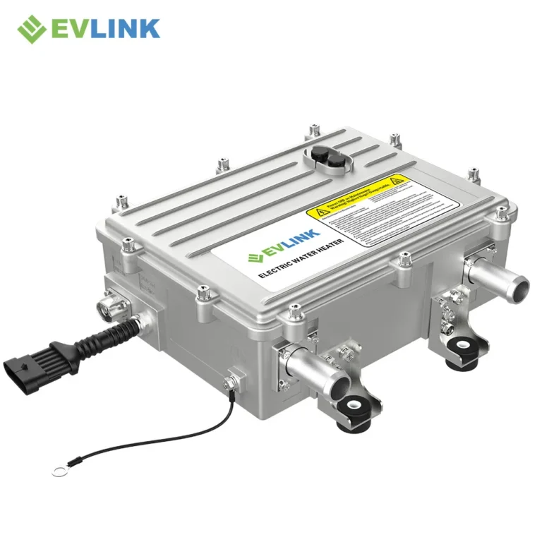
This is the calculation logic we rely on when selecting system configurations. Our liquid-cooled braking resistor (model HVH-R1402) has a rated power of 140 kW and can operate continuously for 20 minutes, meaning it can handle 46.7 kWh (approximately 168 MJ) of energy per operating cycle. A single high-intensity downhill run is sufficient to drive the braking resistor to full load. This rated parameter is determined based on the operating curve for such downhill conditions, rather than on the data listed on the motor nameplate.
Friction braking systems are like sprinters, not long-distance runners.
Brake rotors are designed to handle specific operating conditions: withstanding extremely high power for a very short period, followed by an extended cooling phase. Decelerating from high speeds to a stop falls into this category; however, sustained braking on long downhill stretches is entirely different—it requires the rotor to withstand a moderate load continuously over an extended period without any cooling intervals.
During sustained braking, the temperature of the brake rotors and pads rises until it exceeds the effective operating range of the friction material. At this point, the brake pedal travel increases, braking distance lengthens, and wear accelerates, leading to premature replacement costs. Drivers refer to this phenomenon as “fade.” Replacing brake pads of any material will not resolve this issue, because the root cause lies not in friction but in heat dissipation: brake rotors rely on the air surrounding the wheels to dissipate heat; however, during a slow descent—precisely when heat input is sustained for the longest duration—the cooling effect of airflow is at its weakest.
Therefore, relying on the “friction braking system” to handle braking on long downhill sections means converting 40 kWh of energy into heat—heat that must be dissipated by the four-wheel braking system, which was originally designed only for brief stops. Although these brakes remain the final line of defense for safety, they are clearly not the appropriate tools for sustained energy dissipation. We have previously discussed this issue of operational mismatch from the perspective of dimensional design, specifically in the article “How Duty Cycle Determines Braking Resistor Specifications.”
Braking resistors serve as pre-configured energy overflow channels.
Connected to the DC bus, braking resistors provide a controlled discharge path for energy that cannot be fed back into the system. When the inverter cannot feed current back to the battery pack, the switching device directs the current through the braking resistor; at this point, the energy is converted into heat and enters the coolant circulation system, rather than accumulating on the brake discs. For information on the operating principle of the braking resistor itself, please refer to the section titled “How Electric Vehicle Braking Resistors Work”; this article focuses on where the energy goes, rather than the conversion mechanism.
The liquid-cooling system ensures that this energy dissipation path can operate continuously. Take the HVH-R1402 model as an example: it is a resistor unit with a resistance of 2.24 Ω (at 25 °C cold state, with a tolerance of ±10%), suitable for 450–850 V DC busbar systems; it has an IP6K9K protection rating and an operating temperature range of -40 to +85 °C. The unit is equipped with a DN32 coolant connection, capable of transferring heat to the vehicle’s cooling circuit at a flow rate of 172 L/min or higher; this heat is continuously dissipated through a radiator throughout the descent. Additionally, a built-in NTC sensor monitors its temperature, while a high-voltage interlock (HVIL) mechanism ensures that the connector is securely in place. The bus voltage determines the power limit of this circuit, as the power dissipated through a fixed resistor follows the formula P = U²/R. At a bus voltage of 450 V, the same 2.24 Ω resistive element can deliver approximately 90 kW of power; at 850 V, it can deliver approximately 323 kW of power. Actual power output is regulated via switch control to meet the actual demands of the downhill driving conditions. Although the resistive elements are identical, their power margins vary significantly. For this reason, the voltage range (voltage window) is one of the first parameters we need to confirm.
Resistor specifications should be determined based on downhill driving conditions rather than motor parameters.
Our selection recommendation remains consistent: please disregard the motor’s peak regenerative power and provide the relevant parameters for the downhill section directly. Even if two trucks are equipped with the same motor, the resistor specifications they require may be completely different, as load conditions depend on the vehicle’s gross weight, the gradient, the length of the descent, and the expected descent speed. If the most demanding descent lasts only two minutes, a smaller resistor—or even a combination of friction and electric braking (friction-electric braking control)—may be sufficient—and we will advise you accordingly. However, if it is winter, the vehicle is fully loaded, and it must travel down a slope for as long as twenty minutes, then the braking resistor is no longer merely an “accessory”; it is the key to ensuring the vehicle maintains a controlled speed throughout the entire descent from the top to the bottom of the slope. For information on how to determine the specifications of a braking resistor for electric buses or trucks, please refer to the complete calculation method.
Frequently Asked Questions
Does energy recovery (regenerative braking) only cease to function when the battery charge reaches 100 per cent?
Not at all. The battery’s ability to accept a charge gradually decreases before it is fully charged. Therefore, on a cold morning, even if the battery charge is only 92 per cent, it may be able to accept less regenerative energy than a battery at normal temperature with a charge of 70 per cent. Please plan your journey based on the ‘decline in charge acceptance’ rather than relying solely on the charge level displayed on the dashboard.
If all the energy is ultimately converted into heat, is energy recovery still worthwhile?
Absolutely. The resistor is only responsible for handling the ‘excess’ energy that the battery cannot accept. The energy that the battery can absorb has been recovered and reused; the resistor, meanwhile, handles the remaining energy—which, without this device, would act on the brake discs in an uncontrolled manner, leading to accelerated wear.
Can the resistor alone keep the lorry stable on a gradient?
The resistor handles continuous resistive loads—the very type of load most likely to damage the friction braking system. The friction braking system, on the other hand, is responsible for bringing the vehicle to a complete stop, holding it stationary and reversing. The division of labour between the two depends on the duration of application: short-term braking (measured in seconds) is handled by the friction brake discs, whilst long-term braking (measured in minutes) is handled by the resistor.
Provide us with your downhill gradient data and we will carry out a calculation and analysis for you.
Are you selecting a lorry or coach for a route that includes long, steep downhill gradients? Please provide the following information: the vehicle’s gross vehicle weight; the gradient, length and target downhill speed of the longest downhill section; the DC bus voltage range; the available coolant flow rate and inlet temperature; and the ambient temperature range. Based on these five pieces of input data, we will carry out resistor selection calculations for the most demanding downhill conditions you face; if our assessment indicates that no resistors are required, we will inform you accordingly.