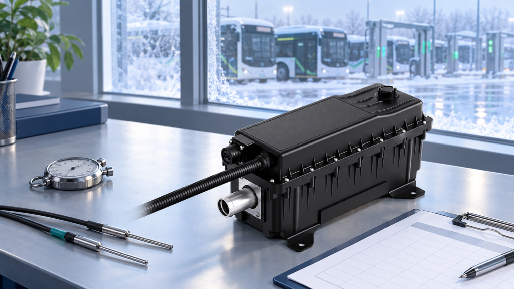
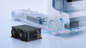
Define repeatable warm-up response evidence for an HVCH without confusing heater output, coolant temperature and vehicle readiness.
A high-voltage coolant heater’s warm-up response should be compared against a defined test, not a promise that it heats a vehicle in a fixed number of minutes. Specify the initial conditions, the event that starts the clock and the temperature or readiness condition that ends it. Otherwise, two valid results may describe different jobs.
For electric buses and trucks in cold climates, distinguish heater response, coolant-loop warm-up and battery or cabin readiness. This guide helps OEM engineers and technical buyers prepare a repeatable acceptance brief. It does not prescribe a universal battery temperature or claim a measured EVLINK warm-up time.
Separate the three response questions
Heater response concerns how the selected unit responds to an accepted command under its permitted electrical and coolant conditions. Define which feedback signals and measured values will be used. A command timestamp and a measured power timestamp are not necessarily the same event.
Coolant-loop warm-up concerns the installed circuit: the fluid, components, flow path, valves, heat losses and connected loads. A temperature at the heater outlet describes that location. It does not, by itself, establish the temperature of every battery module.
Vehicle readiness is the actual operating objective. The battery manufacturer may define conditions for charging or departure, while cabin requirements concern a different load and endpoint. Agree those requirements separately before choosing a heater from the high-voltage coolant heater range.
Make the starting conditions comparable
Ask each supplier to report the starting state with the response result. At minimum, define ambient temperature, the initial temperatures at the agreed measurement points, coolant specification and quantity, circuit layout, flow, valve state and the connected thermal load. Record whether the system has completed a defined cold soak or is starting from a warmer condition.
Include the electrical supply available at the heater terminals and the requested operating mode. An architecture described as 400V or 800V is not enough to define every test condition. Use the exact configuration’s approved voltage range and operating limits; see the HVCH voltage-matching guide.
For supplier comparison, do not silently change the fluid, target, heat load or circulation condition between runs. If an installation requires a different setup, show the difference in the report instead of presenting the results as directly equivalent.
Agree where the clock starts and stops
Choose a start event the test system can record reliably. It might be the time a valid enable command is accepted, or a separately defined point when permitted heating begins. Keep preparatory checks, pump operation and communication delays visible rather than removing them from a vehicle-level result without explanation.
Choose an endpoint that answers the buyer’s question. Reaching an outlet temperature, reaching the battery supplier’s approved readiness condition and stabilizing cabin temperature are different endpoints. Identify the sensor or decision signal, the permitted tolerance and any holding period. The vehicle team should approve those details before the test.
Keep the timestamps aligned. Record requested power, measured electrical input, available temperature feedback, coolant flow and relevant fault or limit states on a common timeline. This makes it easier to distinguish a slow thermal response from a delayed command, a changing supply or a control limit.
Use an energy estimate as a check, not a guarantee
For a simplified lumped system, a first estimate is t = Ceff × ΔT / Pnet, where effective heat capacity is in J/K, temperature rise in K and net heating power in W. The resulting time is in seconds. This relation assumes a suitable effective thermal mass, approximately uniform temperature and roughly constant net power.
Net power means heat retained by the defined system after relevant losses and competing loads; it is not automatically the heater’s rated electrical input. The thermal mass may include fluid and components rather than only the coolant. When losses or control output vary substantially, use a time-dependent model or measured data instead of treating this simple estimate as an acceptance limit.
A calculation is useful for identifying an implausible brief or missing input. It does not replace the installed-system test. The electric-bus heater sizing guide covers the operating duty behind selection; the response test then checks the agreed installation and operating condition.
Ask for a response-test evidence pack
- Configuration: heater part and revision, vehicle circuit drawing, coolant, instrumentation and control calibration.
- Initial state: soak procedure, ambient and component temperatures, fluid level and electrical supply.
- Method: approved safety procedure, circulation checks, valve sequence, command profile and recording interval.
- Acceptance: start event, endpoint, tolerance, holding requirement, stop criteria and responsible reviewer.
- Results: measured timelines, repeat runs, deviations and unresolved observations, not only a single headline time.
Define any rerun after configuration changes or service work. If the heater reaches its local target while the intended load does not, investigate the complete circuit and control strategy before changing the acceptance claim. Review coolant-path requirements alongside the HVCH flow and pressure-drop integration guide.
Testing must be performed by qualified personnel under the vehicle and component manufacturers’ approved procedures. Do not bypass electrical, flow or temperature protection to shorten a recorded warm-up time.
Prepare a useful supplier discussion
Send the initial condition, required readiness endpoint, available supply, coolant-loop drawing, fluid specification and operating duty. Separate the performance you require from results that have already been measured. If no validated timing record exists for the proposed configuration, ask for a test plan rather than assuming a catalog description is proof.
Share your warm-up duty and acceptance brief with EVLINK to discuss heater selection and integration inputs. Model-specific operating limits and any performance commitment must be confirmed for the agreed configuration.