Book Appointment Now


EV Coolant Is Not Engine Antifreeze: What to Specify for Battery Thermal Loops
‘Can’t we just use that green liquid?’ We hear this question all the time—perhaps more often than you might imagine. It is usually asked by someone looking at a coolant specification sheet for the first time, whilst busy checking the bill of materials (BOM). The short answer is: no. As for the detailed reasons, that is precisely what this article sets out to explore.
Electric buses and trucks do not have a single, simple cooling circuit; rather, they comprise a complex thermal management system. This system must ensure that the battery pack, electric motors, power electronics – and, in some cases, the passenger compartment – are each maintained within their appropriate temperature ranges. Within the battery cooling circuit, the coolant flows just a few millimetres away from high-voltage components. This fact alone imposes specific requirements on the coolant’s performance.
Colour is not a reliable indicator, and brand names are of limited value as a reference. When assessing coolant specifications for battery cooling circuits, we focus primarily on three core parameters; all other factors are secondary.
1. Electrical conductivity is a safety concern
In internal combustion engines, the electrical conductivity of coolant is virtually irrelevant. No one worries about coolant causing a short circuit, as there are no high-voltage components in the vicinity.
Battery cooling circuits are a completely different matter. Coolant circulates near battery cells, busbars and inverter modules. Should coolant leak onto live surfaces, its conductivity would provide an unintended path for current flow. For this very reason, coolants specifically designed for electric vehicles (EVs) are formulated to have extremely low electrical conductivity; this is also the rationale behind standards such as ASTM D8566 and GB 29743.2. These standards are by no means merely provisions on paper; they represent the dividing line between a ‘leak that merely causes a mess’ and a ‘leak that triggers a high-voltage fault’.
This is also why the cost of remediation is so high once contamination occurs. Tap water contains dissolved minerals, whilst standard engine antifreeze contains ionic corrosion inhibitors. Whichever substance enters the low-conductivity cooling circuit, it will rapidly cause the conductivity to rise. Furthermore, these contaminants cannot be thoroughly removed simply by draining the system. Maintenance personnel usually need to flush the cooling circuit several times with deionised water before refilling it with coolant that meets the specifications. Worse still, when different additive compositions are mixed, solid particles may precipitate, which can block the microchannels inside the battery cold plates. Such blockages often do not become apparent immediately, but manifest as abnormal temperature rises in a particular module during operation… Consequently, in any coolant specification we endorse, the primary parameter appears more as a safety requirement than merely a supplementary chemical specification. Product data sheets on the market typically specify a conductivity of 100 microSiemens per centimetre (µS/cm) or lower; some even specify values below 50 microSiemens per centimetre. We do not promote our own conductivity values as a marketing selling point, as the appropriate value depends on the specific cooling circuit, voltage rating and the insulation requirements set by the vehicle manufacturer. What we insist upon is that this value must be clearly stated, measured in practice and strictly controlled. If a coolant’s product specification does not mention the conductivity specification, then it is not suitable for battery cooling circuits—using it would be tantamount to guesswork.
2. Chemical properties must be compatible with the materials in the cooling circuit
The second aspect we examine is material compatibility. Although these details may seem minor, they are of critical importance. Battery cooling plates are typically made of aluminium; however, in pipe fittings and heat exchangers, the coolant also comes into contact with copper and brass. Seals are most commonly made of ethylene propylene diene monomer (EPDM), silicone rubber or fluorocarbon rubber (Viton). Each of these materials has its own ‘incompatibilities’, and coolants specifically designed for cast-iron engine blocks do not need to take the tolerance of these materials into account at all during formulation and development.
Modern low-conductivity coolants utilise low-ionic corrosion inhibitor formulations; common types include OAT, Si-OAT or P-OAT. These abbreviations are not important in themselves; what matters is their function: they protect aluminium without increasing the coolant’s ionic content, whilst also neutralising brazing flux residues on aluminium cooling plates and heat exchangers. If the corrosion inhibitor formulation is not designed to address flux residues, these minute residues will gradually cause the coolant’s conductivity to rise over time.
When customers provide us with cooling circuit drawings, the bill of materials is one of the first things we examine. This is not out of a love of metallurgy, but because a coolant that performs perfectly in one specific cooling circuit may be entirely unsuitable for another—even if, on paper, the two circuits appear identical. Even with the same ethylene glycol base, different corrosion inhibitor formulations can lead to vastly different results after two years of use. Such issues often only become apparent once the vehicle is in actual operation—which is precisely when you least want to discover them.
3. Service life depends on the overall condition of the system
The third aspect we examine is the ageing process of coolant. As the cooling circuits in electric vehicles (EVs) are sealed and do not come into contact with combustion by-products, the service life of their coolant is indeed longer than that of antifreeze for conventional engines. However, this can easily lead to the misconception that coolant only needs to be topped up once and you can then ‘rest easy’—which is not the case.
Electrical conductivity will drift, corrosion inhibitors will gradually be depleted, and seals will age. Coolant that passes all tests on day one may have deteriorated completely five years later; moreover, the vehicle’s dashboard does not issue a direct warning when electrical conductivity rises. Even if a warning is issued, it often takes the form of a completely unrelated fault code.
Therefore, we should not estimate the service life of coolant based solely on calendar time, but rather regard it as a task requiring continuous monitoring. The electrical conductivity of the coolant should be checked at intervals specified by the vehicle manufacturer. When topping up the coolant, be sure to use the specified grade; never use other off-the-shelf products available on the market at random. Ensure the circulation circuit is sealed and keep detailed records of the coolant added. Whilst these tasks may be tedious, their cost is far lower than the consequences of a battery pack failure.
How the system determines when to heat or cool is a separate topic; we have discussed control strategies in detail elsewhere. The point to emphasise here is simple: the coolant itself is part of the control problem, rather than being independent of it. If the circulation circuit cannot maintain the coolant’s properties, then no matter how superior the controller’s performance, effective temperature control cannot be achieved.
A Brief Overview of the Three Main Categories
It is helpful to summarise the above into three main categories for better understanding. Traditional engine antifreeze is designed for internal combustion engines, for which electrical conductivity is not a significant parameter. Low-conductivity ethylene glycol coolant (which essentially still consists of ethylene glycol and deionised water) is the solution currently used in the indirect cooling circuits of most mass-produced vehicle models—where the coolant flows through a cold plate or cooling jacket without coming into direct contact with the battery cells. Insulating immersion coolants, on the other hand, go a step further by coming into direct contact with the battery cells. Whilst such coolants do exist, they are expensive and fall within the scope of a different system design.
For commercial vehicle projects currently underway, the safest and most conventional choice is the middle option: using a low-conductivity ethylene glycol coolant that meets the three criteria mentioned above in an indirect cooling circuit. The other two approaches are either unsuitable or represent future technological reserves; confusing these categories often results in a project wasting a whole year.
What information to provide to suppliers
If you are requesting a quotation for a thermal management system, or would like us to evaluate an existing system, please include the following eight items of information when submitting your enquiry. Whilst we can proceed even if some of this information is missing, each omission typically requires several rounds of communication to clarify the details.
- Circuit materials: cold plate alloy, metal material of pipe fittings, and seal materials.
- The voltage rating of the battery pack, as well as the maximum voltage encountered in the circuit’s operating environment.
- The ambient temperature range required for vehicle operation.
- Heat and cold sources within the circuit: for example, PTC heaters, heat pumps, chillers, or recovered waste heat from the powertrain.
- Cold plate configuration: i.e. the form of the component through which the fluid actually flows.
- The coolant currently in use (if any), including the type of coolant used for top-ups.
- Seal and hose materials (if different from standard specifications).
- The coolant specification number stipulated by the original equipment manufacturer (OEM) (if applicable).
We have deliberately kept this list concise. Each item on the list will influence the selection of the coolant or determine the verification work we need to carry out prior to final confirmation.
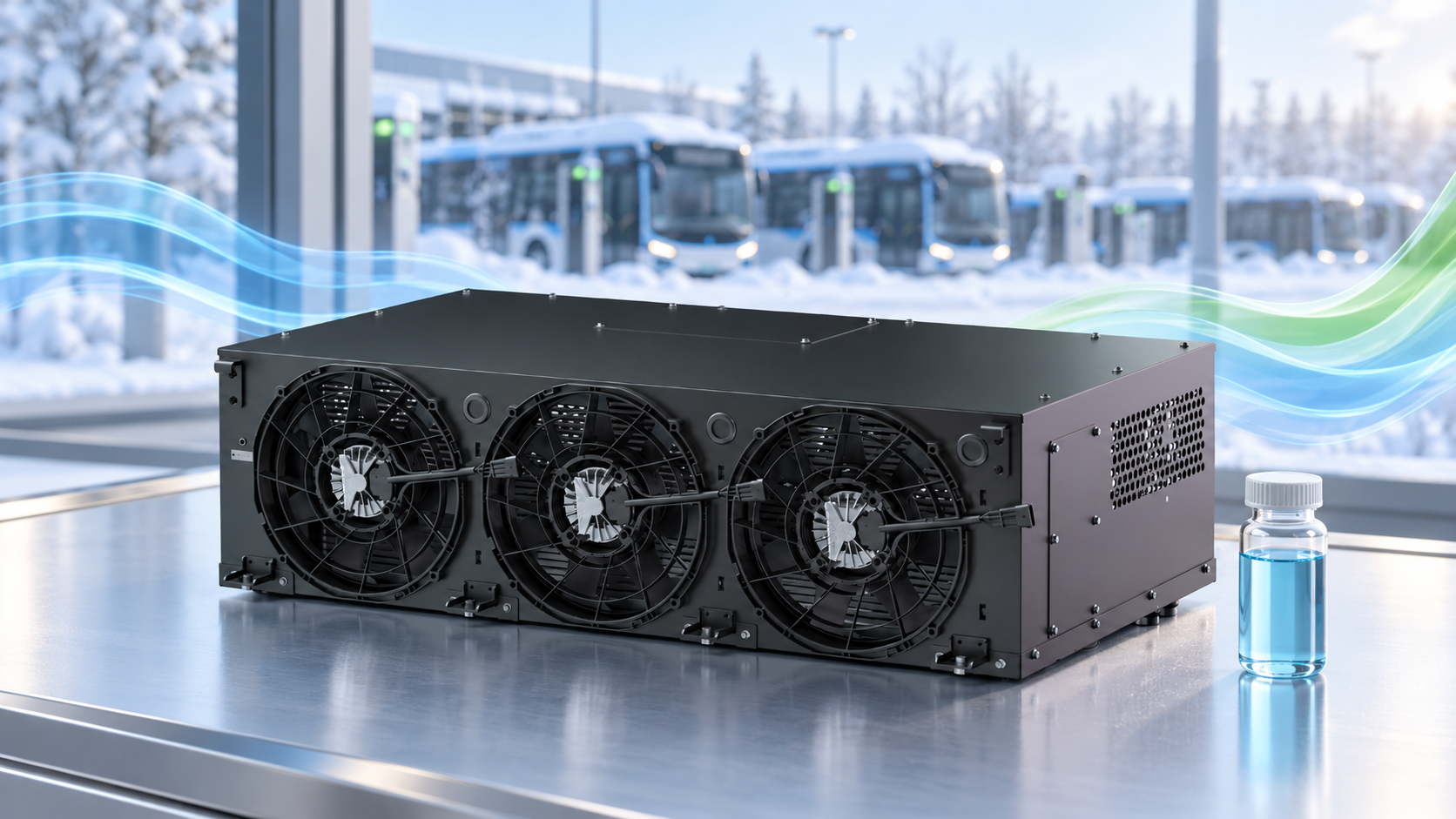
Finally, a note regarding our own hardware. Our ‘three-in-one‘ thermal management controller has a rated operating temperature range of –40 °C to +65 °C; its compressor stage has a power rating of 5 to 10 kW, whilst the heating stage features a dual-channel design—with an 8 kW channel for cabin heating and a 24 kW channel for battery heating. These parameters apply solely to the controller itself, not to the coolant. The selection of coolant must still be assessed based on its own characteristics, in conjunction with the three criteria mentioned above. Should you wish us to carry out a comprehensive assessment of your thermal management circuit and coolant, please submit the aforementioned information via our contact page, and we will discuss this with you.