Book Appointment Now


How Braking Resistors Work in Electric Vehicles
About two weeks after a project begins, we usually receive this question: “We already have a regenerative braking system, so why is there still a resistor listed in the bill of materials (BOM)?”
That’s a good question. Regenerative braking does exist, and on flat roads, it handles most of the braking. However, regenerative braking is essentially a process for charging the battery, and the battery is not a “bottomless pit” that can store an infinite amount of energy. There are three situations in which the battery cannot accept any more energy: first, when the battery is fully charged (lithium-ion batteries can hardly be charged further when fully charged); second, when a downhill section is too long, causing the rate and duration of energy input to exceed the battery’s charging limits; and third, when the battery malfunctions, is too cold, or has limited performance, yet the vehicle still needs to decelerate. In these three situations, there is nowhere for the kinetic energy to be dissipated—and that is precisely why the braking resistor exists.
Step 1: Energy Derives from Mass and Elevation
Braking energy is not initially an electrical quantity; rather, it originates from a heavy vehicle at the top of a slope. The power involved often exceeds people’s expectations.
Take a 40-metric-ton electric mining truck as an example: when traveling at 30 kilometers per hour on a 10% grade, the power exerted by gravity alone on the drivetrain is approximately m·g·v·sin(θ), meaning that throughout the entire descent, a continuous power of about 325 kilowatts is generated. Similarly, an 18-metric-ton city bus carrying passengers traveling at 40 kilometers per hour on an 8% grade will also generate approximately 156 kilowatts of power. These values are unrelated to the rated parameters in motor data sheets; rather, they are directly determined by the grade. All systems downstream of the wheels must be responsible for absorbing, converting, or storing this energy.
Step 2: The Traction Motor Becomes a Generator
During the descent, the traction motor stops consuming electrical energy and instead generates it. The inverter controls the motor to produce reverse torque: the wheels drive the motor to rotate, and the motor generates alternating current, thereby using electromagnetic torque to control vehicle speed rather than relying on traditional friction braking via brake pads.
This is precisely the principle described in various variable frequency drive (VFD) textbooks; it operates exactly the same way in industrial drive systems. In automotive applications, the difference lies in the scale and duration of the energy. A drive system in a factory may only need to brake a load for a few seconds, whereas a truck traveling on a mountain road may need to brake continuously for twenty minutes, during which energy is generated continuously.
Step 3: Energy Reaches the DC Bus in the Form of Current
The inverter rectifies the generated electrical energy and feeds it into the DC link. On the commercial electric vehicle platform we are involved with, the voltage of this link typically ranges from 450 to 850 volts. If the generated regenerative current is not dissipated, the DC link voltage will rise. If left unchecked, the voltage will continue to rise until the inverter triggers a protection circuit due to overvoltage; At this point, the vehicle’s regenerative braking function will fail completely, leaving it to rely solely on friction braking. Obviously, no one wants to discover this situation while driving down a long slope.
Therefore, this energy needs to be absorbed by a load. The preferred option is always the battery—recovering energy through charging and using it for the next uphill climb. This is the most efficient approach; as long as the battery is capable of accepting electrical energy, the vehicle will prioritize this path.
Step 4: When the battery cannot accept energy, the chopper kicks in
This is when the braking resistor comes into play. The braking chopper is essentially a power switch (typically an IGBT in most designs) connected in series between the DC bus and the resistor. The controller monitors the bus voltage in real time. When the battery cannot absorb the regenerative current and the bus voltage exceeds a set threshold, the chopper begins to operate, connecting the resistor to the bus via a pulse-width modulation (PWM) signal. If greater braking force is required, the pulse width increases; if less braking is needed, the pulse width decreases. At this point, the resistor acts as a controllable electrical load, taking on the task of absorbing energy that the battery cannot handle.
From a physics perspective, the resistor operates based on the Joule heating effect. When current flows through a resistor, heat is generated, following the formula P = U²/R. Taking our HVH-R1402 model as an example, its resistance value is 2.24 Ω (cold state, 25°C, ±10%). At a bus voltage of 850 V, it generates a current of approximately 379 A, with a power of about 322 kW; at 450 V, the current is approximately 201 A, with a power of about 90 kW. The chopper controls the average power within the required range by adjusting the PWM duty cycle to precisely match the actual braking requirements when the vehicle is descending a slope.
Engineers often discuss a point on forums—and it makes perfect sense—that a resistor itself does not possess any “control” function. It cannot limit current in any “intelligent” way; rather, it determines the rate at which energy is released from the busbar based on the current voltage level. The actual “decision-making” is performed by the chopper and its controller, while the resistor is responsible for absorbing energy—it must continuously absorb energy at its rated power throughout the entire descent.
Step 5: Heat Must Be Dissipated
Converting electrical energy into thermal energy is only the first—and relatively simple—step in the entire process; the real challenge lies in how to dissipate this heat. This is also the primary distinction between electric vehicle (EV) braking resistors and their industrial “predecessors.”
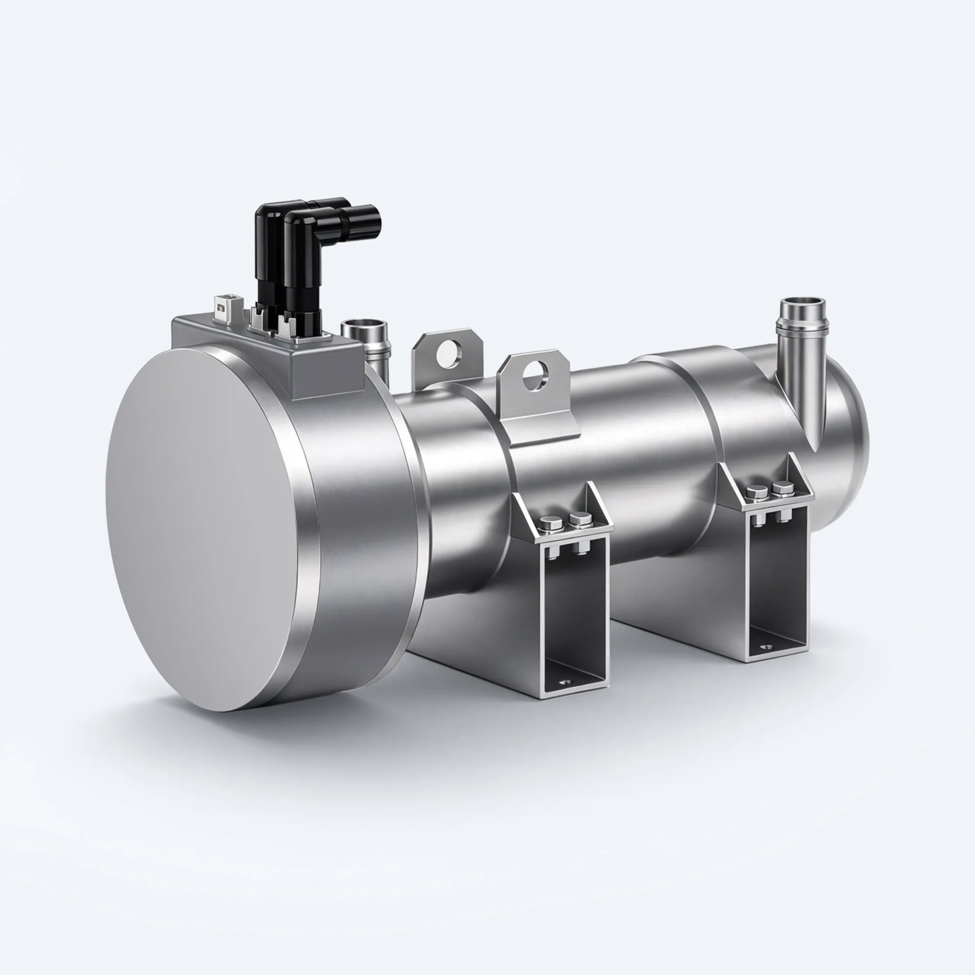
Operating continuously at 140 kW for 20 minutes generates 168 MJ of heat, equivalent to 46.7 kWh of energy. If an air-cooled resistor were installed beneath a truck chassis—in a still, hot, and dusty environment—it would be unable to dissipate this heat effectively. In vehicles of this type, the resistor is liquid-cooled and integrated into the vehicle’s cooling circuit. The HVH-R1402 transfers heat to the coolant via a DN32 connection; to maintain a full power output of 140 kW for 20 minutes, the coolant flow rate at the resistor’s connection must be at least 172 L/min.
There are two effective ways to dissipate the heat in the cooling circuit: under normal conditions, the heat is dissipated into the air via the radiator; on cold mornings, the warm coolant can be directed to the battery heating system or the cabin heating system, thereby achieving “reuse” before the braking energy is completely dissipated. Heat recovery involves unique design considerations, which we will discuss in a separate article in this series. The core message of this article is that the resistor is not a simple “add-on” component, but rather a critical node in the vehicle’s thermal management system.
Safety Circuits Surrounding It
Two signal paths ensure the reliable operation of the entire system. An NTC sensor inside the unit feeds back the component temperature to the vehicle controller, enabling the vehicle to proactively reduce braking power or engage friction brakes before overheating occurs. The high-voltage interlock (HVIL) circuit is used to verify that the high-voltage connector is fully seated; should the connector become loose or malfunction, the vehicle can respond before the chopper supplies power to the resistor. From an electrical standpoint, a resistor may seem like a simple device, but in automotive applications, it must be integrated into a monitored circuit—this is the standard design requirement. We have discussed selection errors in detail in our “Guide to Common Selection Pitfalls,” which includes “omitting the wiring for these two signals”—and this is by no means a coincidence.
Next Steps
If you are in the process of selecting a system, we recommend following this procedure: First, use the U²/P formula to calculate the resistance value that meets the bus voltage range; next, refer to our “Voltage Matching Guide” to verify whether this resistance value complies with the upper and lower limits of the voltage range; finally, determine the continuous power rating based on the most severe downhill operating conditions (see the complete selection guide for details). We will elaborate in detail on the chopper architecture behind “Step 4” and why liquid cooling is used instead of air cooling in subsequent articles in this series.
Alternatively, you can directly provide the relevant parameters for the downhill driving conditions: vehicle mass, gradient, slope length, vehicle speed upon entering the slope, and bus voltage range. We will base our calculations on the HVH-R1402 model (2.24 Ω, 450–850 V DC, 140 kW continuous power (20 minutes), IP6K9K protection rating, validated through 25 tests and 9,360 endurance cycles) and inform you whether it meets your application requirements. The minimum order quantity for this product is 10 units, with a lead time of one week. For product details, please refer to our braking resistor page.
Frequently Asked Questions
Since electric vehicles have regenerative braking, why are braking resistors still needed?
Because regenerative braking essentially charges the battery, and the battery cannot always accept electrical energy. When the battery is fully charged, its ability to accept a charge is nearly zero; on long downhill stretches, the energy generated often exceeds the battery’s charging rate; furthermore, if the battery malfunctions or is at a low temperature, it may be completely unable to accept electrical energy. Braking resistors provide a controlled path for dissipating this excess energy (converting it into heat), thereby ensuring that the vehicle retains full electric braking capability in all of the above situations.
How much power can the braking resistor actually absorb?
It can absorb all the energy generated during descent that the battery cannot accept. Its instantaneous power limit is determined by the formula P = U²/R: taking a 2.24 Ω resistor as an example, at a bus voltage of 850 V, its power can reach approximately 322 kW; at 450 V, the power is approximately 90 kW. The average power output can be adjusted via the duty cycle of the chopper’s PWM (Pulse Width Modulation). Additionally, the resistor has a “continuous rated power” determined by thermal limits—for example, the HVH-R1402 model has a continuous rated power of 140 kW (sustainable for 20 minutes), depending on the cooling circuit’s ability to dissipate heat.
Where does the heat generated by liquid-cooled braking resistors go?
The heat enters the vehicle’s cooling circuit. It is then dissipated into the outside air via a radiator; in cold environments, this warm coolant can also be directed to the battery pack or the passenger compartment for heating. In either case, the heat is ultimately dissipated through the vehicle’s shared cooling system. For this reason, braking resistors must have a reliable coolant flow rate (for our products, for example, the flow rate must be at least 172 L/min) and cannot rely solely on fan-assisted cooling.