Book Appointment Now


BTMS Refrigerant Circuit vs Coolant Loop: An OEM Integration Guide
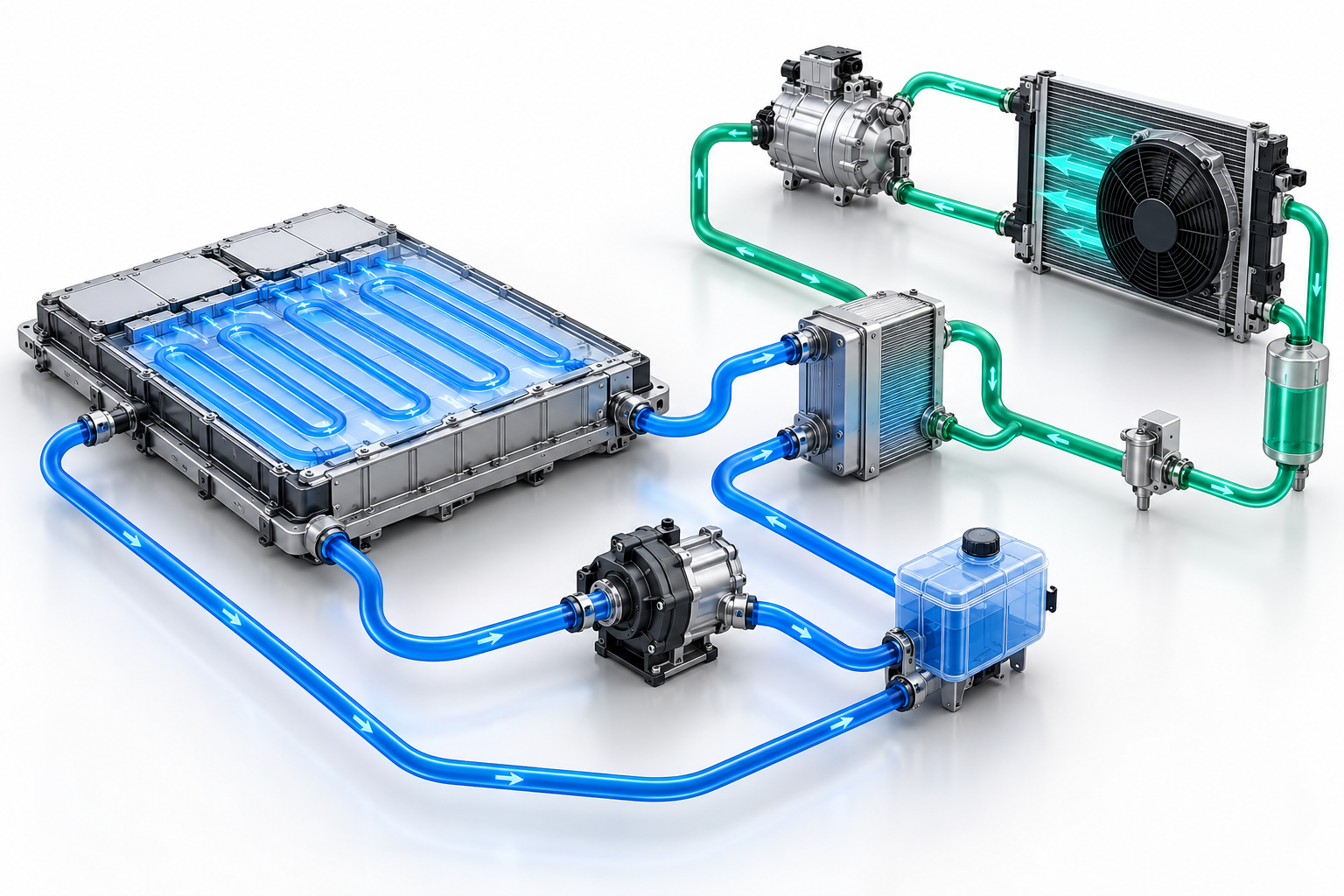
Engineering illustration of a commercial EV battery coolant loop coupled to a separate refrigerant circuit through a chiller.
The refrigerant circuit and the battery coolant circuit within the Battery Thermal Management System (BTMS) are distinct components of the same thermal management architecture. The coolant circuit is responsible for transferring heat between the battery, water pump, valves and heat exchangers; whilst the refrigerant circuit dissipates or absorbs heat via the vehicle’s heating, ventilation and air conditioning (HVAC) system. Confusing the two often leads to errors in system selection, control strategies and the commissioning phase.
For electric lorries and coaches, system integration is by no means as simple as selecting a chiller. Before finalising the component configuration, engineering teams must clearly define the heat transfer paths, operating modes, interface specifications and control responsibilities for each component. This guide aims to provide original equipment manufacturers (OEMs) with a generic working framework, without prescribing specific refrigerant types, battery chemistries or vehicle voltage levels.
Functional Analysis of Each Circuit
Battery Coolant Circuit
The coolant circuit circulates a water-ethylene glycol mixture or other approved heat transfer medium through the battery cold plate. Its primary function is to extract heat from the battery cells and transfer it to equipment capable of dissipating or recovering this heat. This circuit typically comprises a cold plate, a water pump, an expansion tank (or venting device), valves, hoses, temperature sensors and a liquid-side heat exchanger.
The coolant circuit determines the flow distribution on the battery side, pressure drop, local temperature distribution and the risk of air entrapment. A water pump that meets flow rate specifications during bench testing may fail to achieve the expected flow rate in actual vehicle installation once hoses, pipe fittings and cold plates are connected. Therefore, assessments should refer to the complete resistance curve rather than focusing solely on flow rate values under a single design condition.
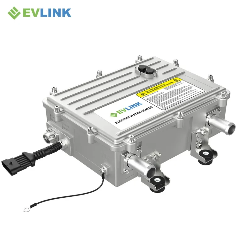
In practice, the coolant circuit is also where the BTMS unit itself is usually specified. EVLINK’s liquid-cooled units, for instance, are offered in 3 kW, 5 kW and 12 kW cooling capacities and operate directly on the vehicle’s 400–860 V DC bus, whilst their enclosures are sealed to IP67 for underbody mounting on commercial vehicles.
Refrigerant Circuit
The refrigerant circuit transfers heat through the processes of compression, condensation, expansion and evaporation. When a ‘liquid-refrigerant’ chiller is employed, the unit couples the two circuits whilst ensuring that the respective fluids do not mix. The heat exchange capacity on the refrigerant side depends on the compressor operating conditions, condenser airflow, expansion control strategy, ambient conditions, and load competition arising from the HVAC system whilst meeting the cabin’s requirements.
This means that relying solely on the rated parameters stated on the chiller’s nameplate does not guarantee that the battery will be adequately cooled under the vehicle’s most severe operating conditions. A comprehensive verification of heat exchange capacity must be carried out, taking into account the actual refrigerant inlet conditions, coolant inlet temperature, coolant flow rate, ambient conditions and concurrent cabin heat loads.
Why vehicle manufacturers’ teams should distinguish between the two during the design phase
Distinguishing between the two circuits helps to clarify the responsibilities of each component and simplifies the fault diagnosis process. For example, battery engineers can use this to set the permissible temperature range and temperature differential limits for the coolant. HVAC engineers are responsible for defining the refrigerant’s operating range and available cooling capacity; control engineers are responsible for coordinating various requirements, constraints and fail-safe modes. Subsequently, vehicle-level integration validation ensures that the combined system operates correctly under various operating conditions, such as idling, fast charging and sustained driving loads.
A practical interface specification should clearly define the responsibilities of each controller regarding water pump, valve and compressor requests, fan requests, and arbitration of thermal management modes. Furthermore, it should define how the system should respond when one circuit is operating normally whilst the other is unable to meet the expected heat exchange requirements.
Five operating modes that must be clarified prior to selection
Battery cooling whilst driving: Specify battery heat generation, ambient temperature range, vehicle speed and condenser airflow conditions.
Fast-charging cooling: Specify the charging power curve, airflow conditions whilst stationary, and any thermal management requirements that may arise in the passenger compartment at this time.
Cold start preheating: Specify the heating method to be used, such as coolant heating, heat pump operation or other heat sources. Where coolant heating is selected, the heating capacity must be matched to the pack size and the lowest expected ambient temperature; the PTC heaters integrated in EVLINK’s units, rated at 5 kW or 6 kW on the smaller models and 8 kW on the 12 kW model, illustrate the range typically required for bus and lorry battery packs.
Competition between cabin and battery demands: When both circuits simultaneously require high load capacity, specify the priority rules.
Derated operation: Specify the permissible extent of power derating, as well as safety response mechanisms in the event of failures in water pumps, sensors, fans, compressors or valves.
Information required for a reliable Battery Thermal Management System (BTMS) integration assessment
This should be based on operational data varying over time, rather than relying solely on peak data. Key input parameters include: the battery’s heat dissipation over time, the target coolant inlet temperature, the permissible cell temperature difference, the flow rate range (minimum and maximum values), the total pressure drop across the circuit, coolant specifications, fill volume, ambient temperature range, charging conditions, and the expected vehicle operating conditions (duty cycle).
On the refrigerant side, the following must be recorded: refrigerant type, compressor operating characteristic map (MAP), condenser performance, expansion valve control strategy, chiller boundary conditions, and the refrigeration capacity reserved for cabin comfort. If any of the above parameters are missing, they should be marked as ‘to be determined’; under no circumstances should nominal values from product catalogues be used to fill in the gaps.
Common integration pitfalls
Relying solely on the chiller’s rated capacity: rated operating conditions may not correspond to the vehicle’s actual operating conditions.
Failing to select water pumps in conjunction with the full system characteristic curve: hoses, fittings and the actual pipework layout may alter the system’s operating point.
Ignoring air bleed issues: residual air within the system reduces heat exchange efficiency and may cause unstable sensor readings.
Assuming equal flow rates in parallel branches: Differences in manifold geometry and resistance across branches may result in uneven flow distribution.
Focusing solely on cooling performance whilst neglecting control mode switching: Mode switching may trigger temperature overshoot or cause frequent compressor start-stop cycles.
How to validate a coupled system
Validation work should combine component-level testing with vehicle-level testing. Firstly, verify the flow rate, pressure drop, leak-tightness, venting conditions and the validity of sensor data on the cooling side. Subsequently, perform characteristic mapping on the chiller across the coolant and refrigerant conditions that the vehicle will actually encounter, and finally subject the complete system to vehicle-level scenarios covering charging, driving, idling and hot and cold soaking.
Throughout such validation, the control interface between the BTMS unit and the vehicle deserves particular attention, since mode arbitration is executed through it; units communicating via CAN 2.0, as the current EVLINK range does, allow the vehicle controller to command heating and cooling modes and to read back diagnostic states from the pump, valves and sensors.
For OEM teams currently defining a battery thermal management architecture, EVLINK can review the operating-point data described above and advise whether a 3 kW, 5 kW or 12 kW unit, or a configuration with supplementary PTC heating, is appropriate for the vehicle in question. Enquiries should include the duty cycle, the target coolant inlet temperature, the permissible cell temperature difference and the ambient temperature range, as single peak values are insufficient for a reliable recommendation.
Frequently Asked Questions
Does the battery coolant enter the refrigerant circuit?
No. In a chiller-based architecture, the two fluids remain separated by the heat exchanger. Heat crosses the exchanger; the fluids do not mix.
Can one cooling-capacity value cover every vehicle condition?
No. Available capacity changes with coolant temperatures and flow, refrigerant state, compressor speed, ambient condition, condenser airflow and competing cabin load.
Which circuit should be sized first?
Neither should be finalised in isolation. Establish battery heat load and allowable temperatures, build the coolant hydraulic model, then verify that the refrigerant circuit can deliver the required capacity at matching boundary conditions.