Book Appointment Now


Every braking resistor RFQ we receive contains the same two numbers: a DC bus voltage and a braking power. The buyer wants one number back — the resistance in ohms. Search for the formula and you get R = U²/P within seconds. It looks like a five-minute calculation.
It is not. The formula is correct, but in an electric vehicle the U and the P in it mean different things than in the textbooks. Almost every formula guide online was written for industrial variable-frequency drives: 480 VAC in, 780 VDC brake chopper turn-on, a 5 HP motor. Your 750 V battery pack and 100 kW of braking power do not fit that table. Use the wrong U and the resistor you order either cooks the chopper or cannot absorb the power you need.
Here is how we actually work through it with customers.
The formula computes the maximum resistance that can still absorb your peak braking power. Go above it and the chopper, fully on, cannot pull the power you asked for. The resistor survives — nothing burns — but your braking comes up short.
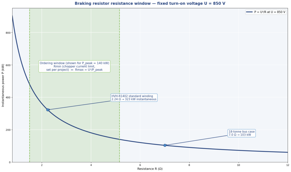
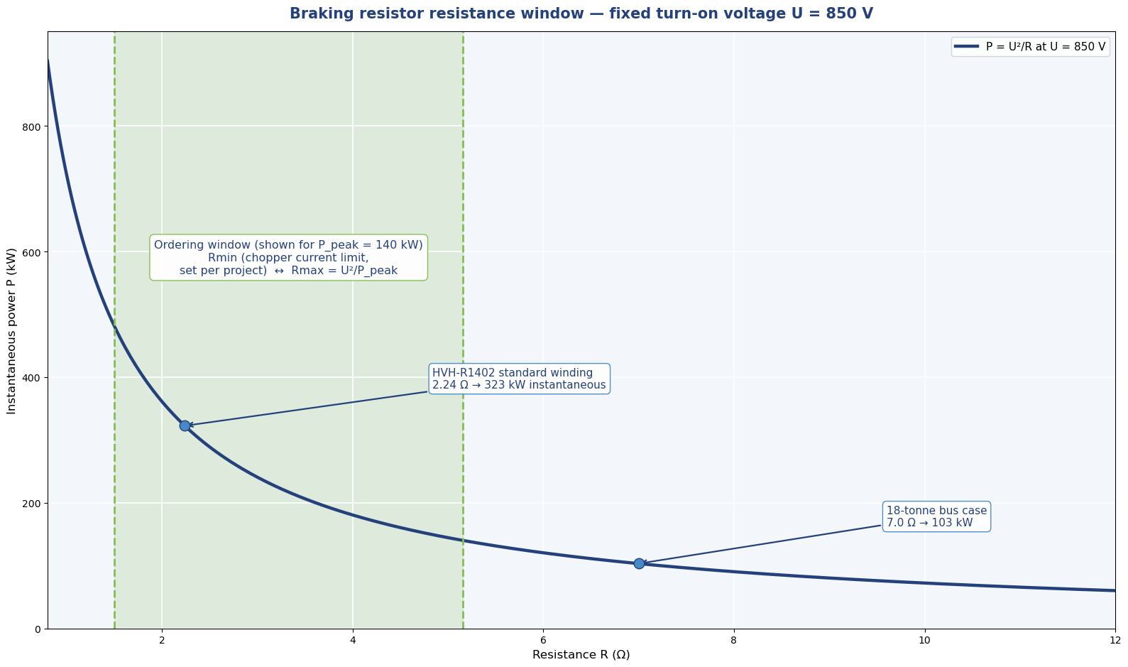
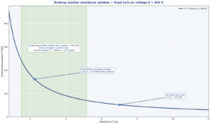
The real answer is a window, not a number. The top of the window comes from the formula. The bottom comes from the brake chopper: resistance too low means current too high for the switching device. Between them sits the value you actually order. Everything below is how to place that window correctly.
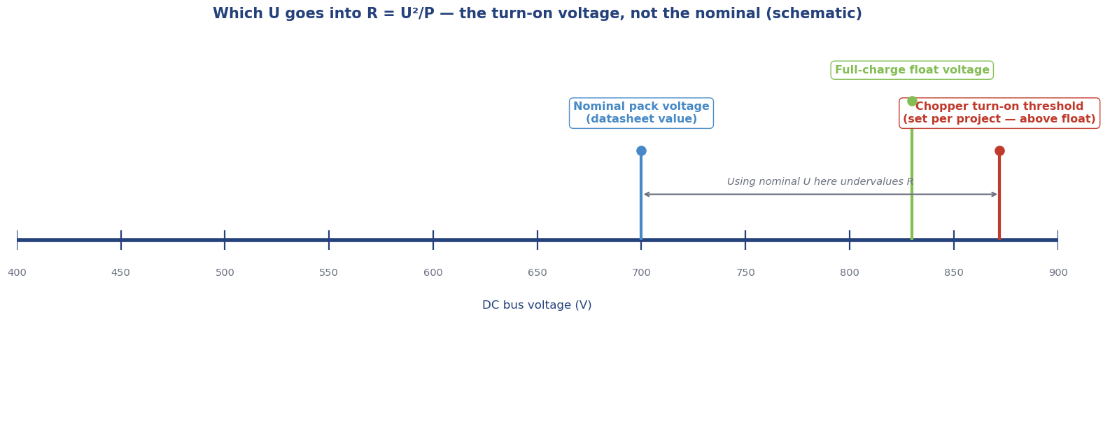
The U in the formula is the DC bus voltage at the instant the brake chopper turns on. Not the nominal pack voltage printed on the battery datasheet.
In the VFD world this is easy because the numbers are fixed. Drive manufacturers publish turn-on tables: 240 VAC mains means the chopper fires at about 390 VDC, 480 VAC means about 780 VDC, and so on. You look up your drive, you get your U, done.
Electric vehicles have no such table. The chopper’s turn-on threshold sits above the pack’s full-charge float voltage and is set per project — it depends on the battery chemistry, the BMS charge limits, and how much headroom the vehicle program wants before the resistor starts working. Two trucks with the same nominal 750 V pack can have different turn-on voltages.
This matters more than it looks because voltage is squared. A 10% error in U becomes a 21% error in power for the same resistance. Pick U too low and the calculated resistance comes out small; the real current at the real turn-on voltage then exceeds what the chopper can switch. Pick U too high and the resistance comes out large; the resistor cannot absorb the peak power and the excess goes to the friction brakes — or nowhere good.
Rule of thumb we give every customer: confirm the chopper turn-on voltage first, in writing, before anyone calculates R. Nominal pack voltage is not a substitute.
Once U is fixed, the window follows from two constraints that the drive industry has used for decades. Schneider Electric’s brake resistor FAQ states them plainly, and they apply to EV choppers just as well:
Rmax = U² / P_peak. Above this resistance, the chopper cannot absorb your peak braking power even at full duty. No damage — just derated braking.
Rmin comes from the chopper’s current limit. I = U / R. Below this resistance, the current through the switching device exceeds what it can handle, and that failure is not graceful.
Let us run it on real hardware. Our HVH-R1402 series is wound at 2.24 Ω (cold, 25 °C, ±10% tolerance) for 450–850 V DC systems, rated 140 kW continuous for 20 minutes:
The lesson from the two ends of the voltage range: always verify the window at both extremes of your bus voltage, not just at nominal. A resistance that looks right at 750 V nominal can be wrong at 850 V full charge or 450 V depleted.
The P in R = U²/P is peak instantaneous power — the most the resistor must absorb in a single braking event. It is not the average power, and it is not the motor’s rated power.
Average power and duty cycle decide something else entirely: the resistor’s thermal rating, the wattage it must survive over time. That is the other half of sizing, and it is where liquid cooling earns its place. A resistor that handles 300 kW for ten seconds is a very different thermal design from one that handles 140 kW for twenty minutes. Our companion sizing guide walks through the continuous-power method; the formula here only places the resistance window.
Three mistakes we see in incoming RFQs, in order of frequency: using nominal pack voltage instead of turn-on voltage; using average power instead of peak power in the formula; and forgetting the ±10% cold tolerance, which squeezes the window tighter than the calculation suggests.
If you want us to check your resistance window, send four things and our engineers will come back with a configuration:
Why is U squared — does a small voltage difference really matter?
Yes. Power scales with the square of voltage, so a 10% difference in U means a 21% difference in power for the same resistance. That is why “which voltage” is the first question, not a detail.
Can one resistor cover my whole 450–850 V range?
Ours does — the 2.24 Ω standard winding is verified at both ends of the 450–850 V window, as the worked example above shows. Other voltage ranges get their own winding on the same platform; resistance is wound to order, not picked from a catalog.
What if my calculated R is below the chopper’s minimum?
Three options, in the order we try them: re-check the power figure (peak vs. average confusion causes most of these), consider series windings, or revisit the chopper selection. Do not just install it and hope.
Is R = U²/P the whole sizing story?
No. It places the resistance window. Thermal sizing — continuous power, duty cycle, cooling — is the other half. Start with our sizing guide for the thermal method, then use this article for the electrical window.
Send us your bus voltage window and braking power — peak and continuous. We’ll check the resistance window and come back with a configuration.
Define heat pump and HVCH duties for electric buses and trucks. Review supplemental heat, shared-loop priorities, power limits and mode-transition evidence.
Compare BTMS cooling capacity at matched coolant, ambient and electrical conditions. Request the evidence needed for electric bus and truck selection.
Every braking resistor RFQ we receive contains the same two numbers: a DC bus voltage and a braking power. The buyer wants one number back