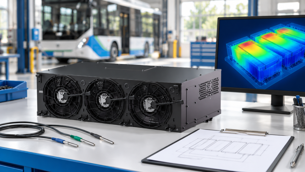
Separate measurement issues, coolant distribution and cooling capacity when investigating uneven battery temperatures in electric buses and trucks.
If one part of a liquid-cooled battery pack stays hotter than the rest, do not assume that a larger chiller is the answer. First check that the temperature readings are comparable, establish a repeatable baseline, and investigate the coolant distribution. This guide helps electric bus and truck OEM teams turn a temperature-spread complaint into an engineering investigation. The battery manufacturer’s limits and released procedures remain the authority for operation and testing.
Define which temperatures you are comparing
Temperature spread is the highest minus the lowest value within a defined measurement set at a given time. Record the sensor locations and synchronization method alongside that result. A coolant outlet reading and a cell-surface reading describe different points in the thermal path; combining them does not establish cell-to-cell uniformity.
Agree on three separate acceptance criteria: maximum temperature, spread across the specified locations, and performance over the required duty cycle. Obtain the limits from the responsible battery and vehicle engineers. There is no project-independent temperature-difference threshold in this guide.
Check the measurement before changing hardware
Confirm sensor identification, attachment, calibration records, units and timestamps using the approved measurement procedure. Compare the BMS data with the defined test instrumentation where the validation plan requires it. Treat an unexplained disagreement as an open measurement issue, not evidence that a component has failed.
Our BTMS temperature sensor placement guide addresses the measurement map. Here, use that map to describe whether the hottest reported location remains the same across comparable runs. Preserve the complete time histories, not only a screenshot of the largest difference.
Build a baseline that can be repeated
Record initial pack conditions, state of charge, ambient conditions, coolant mixture, inlet temperature, load profile and thermal-control commands. Note configuration changes between runs. A charging test and a road-duty test may impose different thermal conditions, so compare like with like before drawing a conclusion.
If a limit is approached or a protection event occurs, follow the approved stop and fault-response procedure. Do not extend a test, open a hot or pressurized circuit, or disable protection to obtain a cleaner data set.
Investigate distribution as well as total flow
Draw the actual circuit, including parallel branches, valves, restrictions and measurement points. Total loop flow does not tell you the flow through every branch. Request branch measurements and the relevant hydraulic design under the same operating conditions before recommending a balancing change.
Published research identifies coolant distribution and cooling-channel geometry as factors in temperature uniformity. That supports investigating the local cooling path, but it does not identify the fault in a particular vehicle. See the study of cooling-plate flow maldistribution and the review of liquid and hybrid battery cooling. Their configurations and results are not EVLINK product specifications.
If the symptom appeared after filling or maintenance, examine the commissioning records. Air removal is a separate controlled task; use the released procedure and our coolant-loop air removal guide as a planning reference, not an instruction to bypass approved service steps.
Choose the next evidence, not a premature diagnosis
| Observed pattern |
Next evidence to collect |
Conclusion to avoid |
| A repeatable hot region |
Sensor checks, local cooling path, branch measurements and assembly records |
The chiller must be undersized |
| All monitored regions rise together |
Heat-load evidence, inlet conditions and cooling-unit operating state |
Branch balancing alone will solve it |
| Spread mainly appears during transients |
Synchronized load, commands and temperature histories |
A steady-state reading proves the full duty cycle passes |
| The pattern changes after maintenance |
Recorded configuration changes and commissioning results |
The original hardware rating is necessarily wrong |
This matrix is an investigation aid, not a fault-code table. More than one mechanism can be present. Label each explanation as a hypothesis until the responsible engineering team has reviewed the supporting evidence.
Separate cooling capacity from delivery
A capacity review asks whether the thermal system can meet the measured load at the specified conditions. A distribution review asks whether cooling reaches the intended locations. Keep both questions open when comparing solutions. Increasing pump command or lowering the coolant target is not an automatic remedy: hydraulic limits, battery requirements and control constraints still apply.
Use the BTMS coolant flow guide for the overall flow task, then return to branch-specific evidence. Evaluate a proposed hardware or calibration change through an approved repeat test with the original acceptance criteria and a recorded configuration.
Prepare an investigation brief for your supplier
Send the circuit drawing, sensor map, synchronized logs, load profile, initial conditions, coolant details and battery limits. Include maintenance history and a list of changes between tests. State what is measured, what is inferred and what remains unknown. This is more useful than requesting extra cooling capacity based only on one temperature screenshot.
Review EVLINK battery thermal management systems, or share your temperature-spread investigation brief with EVLINK. Product suitability and any proposed change must be confirmed against the actual project requirements.