Book Appointment Now


NTC Temperature Sensing and HVIL: The Safety Loop Inside a Braking Resistor
A review of the integration of a braking resistor tends to get bogged down in the same three questions. They seem straightforward, but each one has posed a problem in a real-world project. Can the vehicle cut the power supply to a connector that is not properly plugged in? Is it capable of detecting a rise in temperature during a descent early enough to take action? And when a sensor reading appears to be incorrect, does the controller have a pre-set response, or does the system have to improvise on the fly?
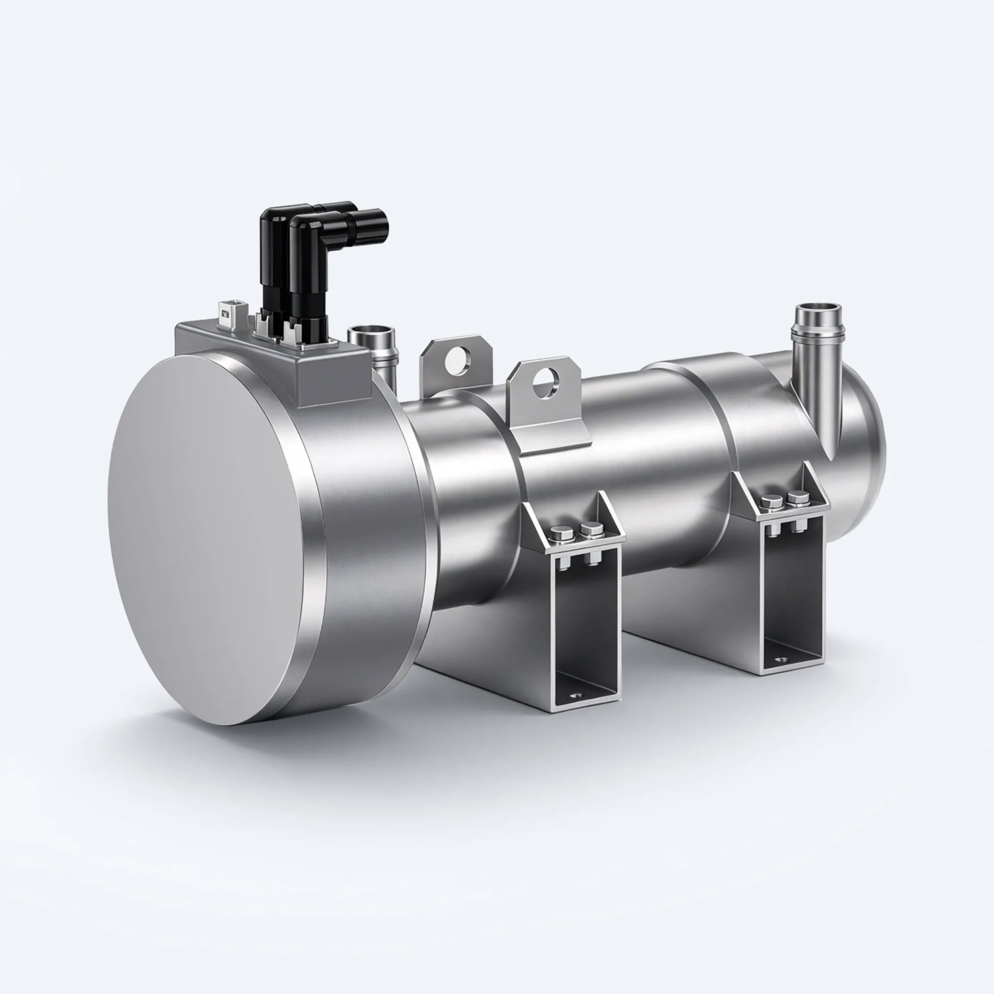
We manufacture the HVH-R1402 liquid-cooled braking resistor for electric buses, heavy goods vehicles, mining trucks and construction machinery, tailored to each project. Its rated power is 140 kW continuous for 20 minutes, 2.24 Ω, 450–850 V DC, IP6K9K, with an operating range of –40 to +85 °C, and it has been validated through 25 tests. These figures describe the unit. They do not indicate whether the vehicle surrounding it is safe. That aspect depends on two signals and one set of protocols: the high-voltage interlock loop (HVIL) provides protection in the moments before current flows; NTC temperature detection provides protection during the minutes whilst current is flowing; and a documented fault map provides protection when a reading ceases to make sense. If any one of these three is missing, the inspection must not give the go-ahead.
The acceptance test table: what to check and what a ‘correct’ result should look like. HVIL loop closed before activation: disconnect a high-voltage connector on first start-up and observe how the vehicle refuses to activate the resistor. A correct result is as follows: no current reaches the resistor due to an open circuit, every time, not just on the first attempt. What is overlooked if this check is omitted: a poorly connected plug that allows charging current to flow until an electric arc occurs. NTC reading under real-world conditions under load: carry out a braking test under load and confirm that the temperature reading varies according to the load. The correct behaviour is as follows: the reading follows the braking effort and stabilises as the load decreases. What is overlooked if this check is omitted: a sensor that exists only on the wiring diagram and nowhere else. Adequate cooling for the duty cycle: compare the flow rate available at the resistor inlet with the 172 l/min required for the full 140 kW cycle over 20 minutes. The correct result looks like this: a temperature trend that stabilises during a sustained decline. What is overlooked if this step is omitted: a rise that never stabilises, which is accurately reported but on which no action is taken. Controller response agreed in advance: the integration document specifies what the controller does in the event of a power reduction, an open-loop condition and a sensor fault. The correct approach is something like this: three written responses, one for each scenario, agreed with the supplier prior to commissioning. What is overlooked if this step is omitted: a fault detected on a slope, with an improvised response on the spot. That table encapsulates the entire article in miniature. The rest explains why each row has its place, with the calculations that determine what is at stake.
Why so much is at stake: 168 MJ in a single descent
140 kW over 20 minutes equates to 140 × 20 × 60 seconds, which amounts to 168,000 kJ, or 168 MJ of heat per unit. Per minute, that amounts to 8.4 MJ. Put another way, a vehicle on a long downhill gradient is asking one resistor to absorb, minute after minute, roughly the energy of a minor car crash every few seconds – and does so without a hitch.
The cooling system works in the same way. At 172 L/min, operating at full load for 20 minutes circulates 3,440 litres of coolant through the DN32 connection. If the circuit cannot provide that flow rate — whether due to a shared pump, a hose that is too long, a sharp bend or trapped air — the rise in temperature will be the first thing to tell you so. And it won’t politely tell you twice.
The calculation of resistance provides a second reason why the control strategy is important, and here we are simply taking it a step further than what had already been set out in our guide to calculating resistance. That guide places the same nominal winding of 2.24 Ω at around 90 kW instantaneous at 450 V and around 323 kW at 850 V, compared with a continuous thermal power of 140 kW. The additional point made in this article is what these two figures imply for the chopper: at 850 V, maintaining an average power of 140 kW out of the 323 kW instantaneous power implies a duty cycle of around 43 per cent relative to the nominal resistance. (Our sizing guide highlights the same ‘voltage window’ effect from the other end: the power at the upper end of the 450–850 V window is approximately 3.6 times the power at the lower end). The rated power of the resistor, the bus voltage and the chopper strategy constitute a single calculation, not three separate lines on the technical data sheet. A safety review that checks the rated power of the resistor without verifying the duty cycle strategy has only checked half the system.
Before current flows: the HVIL loop
The HVIL system answers a single question: are the high-voltage connectors fully mated? A low-voltage signal loop runs through the connectors. In typical HVIL connector designs, the short signal pin breaks contact before the power pins separate, so that a connector that becomes loose opens the signal loop whilst the power pins remain in contact. The vehicle detects the open loop and can refuse to supply power to the resistor before current flows through a faulty connection.
Timing is everything in this case, and it is the aspect that is most often misunderstood. The HVIL is not a fault detector for a braking manoeuvre that is already in progress. It is a gate in the enable sequence. A loose connector detected during a 140 kW braking manoeuvre already poses a risk of an electric arc. A loop checked before activation turns that same fault into a connector issue detected in the workshop.
That is also why bypassing the loop is the most costly shortcut in this article. During installation or commissioning, someone bypasses the interlock to save ten minutes, intending to remove the bypass later. The vehicle then loses its only means of detecting a poorly fitted connector, and this remains the case for the vehicle’s entire service life, not just for that one afternoon. If the loop does not close, the connector is not fitted properly. Fix the connector. Never silence the loop and call it progress.
Our guide to sizing errors includes tried-and-tested checks in its pre-purchase checklist precisely for this reason. The checklist exists because ‘the loop was omitted during commissioning’ is a phrase nobody wants to have to explain following an incident.
Whilst the current is flowing: the NTC loop
Once the resistor is energised, the question changes. It is no longer ‘is everything connected?’, but ‘will this descent end well?’. An NTC sensor located inside the unit communicates the element’s temperature to the vehicle’s controller. In the HVH-R1402 model, this sensor is a 5K NTC element, with an accuracy of ±1 per cent, as stated on the product page. The resistance of the NTC decreases as the temperature rises, so the controller reads a variable resistance and converts it into a temperature trend.
‘Trend’ is the key word, and this is where continuous monitoring proves its worth compared with the industrial alternative. A thermal switch – the sort found in all protection diagrams for braking resistors in variable frequency drives (VFDs) from KEB, Siemens and ABB – provides just one piece of information: whether it is hot or not. It remains inactive, then trips, by which time the vehicle is already at its limit. An NTC sensor provides the slope. The controller can detect how the temperature rises during a descent and begin to react in advance: reducing braking power, engaging the friction brakes and alerting the driver. On a mining truck gradient that generates a sustained load minute after minute, that early response makes the difference between managing a descent and having to react to an emergency upon reaching the bottom.
We must be honest and state this clearly: the sensor detects heat, but it does not remove it. If the coolant flow rate is less than the 172 L/min required by the system, the NTC will show a rise that does not stabilise, and the vehicle will still require a response strategy to act upon. A sensor that nobody takes into account is nothing more than a decoration on the dashboard. The key question during the service is not ‘is the NTC connected?’, but ‘what does the controller do with the reading, at what point, and who has approved it?’.
Correcting the wiring deserves its own section in that review, as it has posed a real problem for some bus programmes. A service bulletin published by a bus manufacturer once attributed a power reduction fault to brake resistor temperature sensor cables that had been swapped at a connector: the protection logic was activated, but based on data from the wrong system. The lesson is universally applicable. A varying reading is not the same as a correct reading. The load brake test shown below checks for variation; the integration document should also confirm that the sensor sends the data that the strategy actually reads to the controller’s input.
When a reading no longer makes sense: fault mapping
The third safety measure is the paperwork, and this is the one most frequently left blank. There are four cases that require written action by the controller before the vehicle leaves the factory, as agreed with the resistor supplier during integration:
- The NTC is installed but has never been connected. Everything works on level ground, so this passes the commissioning stage. It fails on the first real descent, when the vehicle needs a temperature trend and does not have one. Validation question: has it been verified that the reading varies under a real braking load, and not just that it appears on a diagram?
- Cooling is insufficient and the NTC is the only indicator. The flow rate is lower than the load requires, and the temperature rises during the descent rather than stabilising. The sensor fulfilled its function by reporting this. Validation question: what derating or blending step follows the notification, and at what point during the ascent?
- The HVIL loop is bypassed to start the vehicle. A jumper silences the alarm and masks any connector faults that may arise subsequently. Check question: Is there a written commissioning procedure stating that a loop that does not close is a connector fault that must be rectified, and never an alarm that should be silenced?
- A sensor reading appears to be incorrect and no one knows what the correct value should be. An open circuit, a short circuit or a reading that does not vary each require a predefined action from the controller. That assignment is a decision to be made by the vehicle’s controller, and must be included in the integration checklist prior to commissioning, not in a discussion whilst on the road.
Notice what these four cases have in common. None of them is a fault with a resistor. All four are integration gaps, and all four are cheaper to rectify during a service than whilst on the road.
Two tests that check both loops
We recommend carrying out two tests during the first start-up, as they are inexpensive and detect the two most common faults.
Firstly, disconnect a high-voltage connector and observe how the vehicle reacts. The HVIL loop should open and the vehicle should refuse to power the resistor. If nothing happens, the loop is not wired as shown in the diagram. Correct this before carrying out any load tests, as a load test with a faulty interlock is what causes a problem with the connector to turn into an arcing fault.
Secondly, carry out a braking test under load and check that the temperature reading varies with the load. A constant reading under an actual braking load means that the NTC chain is faulty at some point between the sensor and the controller, regardless of what the wiring diagram indicates. A reading that varies with the load means that the entire chain — from the sensor to the controller, via the display or data logger — is functioning correctly.
Ten minutes of testing will provide you with an early warning system for any subsequent descents. If you skip this step, the first real descent will become the test, with a vehicle full of passengers or a loaded lorry acting as a test bed.
What to include with your enquiry
Send us these details and we’ll let you know straight away whether the HVH-R1402 is compatible with your vehicle and what integration requirements you need to meet:
- Bus voltage range and continuous power output with the longest braking cycle. The rated power of 140 kW for 20 minutes is the benchmark; your reduction determines the actual figure.
- Which NTC signal interface your controller expects and what it does with the reading: power reduction steps, warning thresholds, combination with the friction brake.
- How the HVIL loop is connected to your high-voltage system and what your controller does when the loop is opened.
- How the controller responds to a sensor fault: open circuit, short circuit or a reading that does not change.
- Coolant flow rate available at the resistor inlet, compared to the 172 L/min required for full-load operation.
- Chopper configuration: whether your controller already has a chopper output, or whether you require a separate resistor plus chopper setup, or the integrated chopper and brake unit. The safety circuits are the same across all three configurations; it is the wiring that differs.
We manufacture for electric buses, heavy goods vehicles, mining lorries and construction machinery, tailoring our solutions to each project and adapting to the voltage range and operating conditions you actually use. The resistor has a rated power of 2.24 Ω, 450–850 V DC, IP6K9K, operates between -40 and +85 °C and has been validated through 25 tests. These figures describe the unit. The two loops and the fault mapping describe how safety is ensured within your vehicle. Please enquire about both aspects.
Frequently Asked Questions
What is an NTC sensor?
An NTC sensor is a temperature sensor whose resistance decreases as the temperature rises. In the HVH-R1402 model, a 5K NTC element with an accuracy of ±1 per cent transmits the temperature of the resistive element to the vehicle’s controller, which converts the change in resistance into a temperature trend that the controller can act upon before the temperature reaches a limit.
What is an HVIL loop?
A high-voltage interlock loop is a low-voltage signal loop that runs through high-voltage connectors. In typical HVIL connector designs, the short signal pin breaks contact before the power pins separate, so that a connector that becomes loose opens the signal loop whilst the power pins remain in contact. The vehicle detects the open loop and refuses to power the resistor before current flows through a faulty connection.
Do I need both, or is one enough?
Both. NTC cannot tell you a connector is loose. HVIL cannot tell you the resistor is overheating. They watch different failures, on different timescales, and neither covers the other’s blind spot.
Can I use a thermal switch instead of an NTC?
A thermal switch provides a single ‘hot’ or ‘cold’ signal. It cannot indicate how quickly the temperature is rising, nor can it give the controller time to reduce power, apply the friction brakes or warn the driver before the limit is reached. It is an end-of-line device, not a control input. The NTC’s trend and the controller’s programmed response to it are what make the system manageable during a prolonged descent.
What happens if the NTC never connects?
Everything works on level ground, so the commissioning test is passed. However, it fails on the first actual descent, when the vehicle needs a temperature trend but does not have one. The load braking test exists precisely to detect this specific scenario.
What should the vehicle do when the HVIL loop is open?
The vehicle must refuse to supply power to the resistor and treat the open loop as a connector fault that needs to be checked, not as an alarm to be ignored. The exact response sequence is determined by the vehicle controller’s strategy, agreed upon at the time of integration, before the system enters service.
Project data checklist (to be sent alongside your enquiry): bus voltage range; continuous power and maximum braking time; controller NTC interface and response strategy; HVIL wiring and open-loop response; behaviour in the event of sensor faults; available coolant flow rate; chopper status (existing output / split / integrated). Product details: braking resistor page. Related reading: sizing error guide (the two points on your pre-purchase checklist), how braking resistors work (the overview of the safety loop that this article expands upon), sizing guide, U²/P resistor calculation.