Book Appointment Now



Battery Pack Thermal Management: An Interface Checklist for Commercial EV Buyers
Battery pack thermal management is most effective when the battery supplier and vehicle team agree on the boundaries before they compare equipment. A cooling unit cannot be selected from battery capacity alone. The decision also depends on the battery’s permissible conditions, the heat entering the circuit, the installed coolant path and the controller responsible for each operating mode.
For an electric bus or truck project, start with an interface record that both the battery and thermal-system suppliers can review. Record the exact configuration and mark unanswered items as pending.
1. Establish the battery’s operating boundary
Ask the battery supplier for the applicable temperature limits, measurement points and restrictions in driving, charging, parking and any preconditioning mode. Confirm which conditions affect charging permission or available power. Different battery configurations may have different requirements; do not apply a generic temperature target across models.
Identify which measurements describe the pack, which describe individual modules, and which controller interprets them. A coolant temperature reading can help diagnose the circuit, but it is not automatically a measurement of the hottest cell.
2. Define the thermal duty by operating mode
Obtain the heat-load information the battery supplier can provide, together with the time history and the assumptions behind it. A short peak, a long climb and a charging session can demand different responses. Identify additional heat sources connected to the same circuit and avoid counting the same load twice.
Compare candidate system capacity at the required coolant and environmental conditions. A headline kilowatt figure without its operating point cannot establish whether the installed system meets the duty.
3. Separate total flow from pack flow
Record the circuit diagram, coolant formulation, pumps, valves, hoses, cold-plate connections and any parallel battery branches. The pump’s catalogue rating is not necessarily the flow at the installed operating point, and total circuit flow does not show how flow is divided between packs.
Agree how branch flow and pressure drop will be assessed under each relevant valve and pump state. Published pack-level modelling shows that coolant distribution can influence temperature uniformity, but a study of one geometry does not prove the behaviour of another vehicle. Use the actual battery supplier’s flow limits and released interface drawings for selection.
4. Assign control and protection responsibilities
Write down who requests cooling or heating, who commands the pump and valves, where battery limits originate, and what feedback confirms the actual state. Confirm signal definitions, hardware and software versions, timing, diagnostics and responses to invalid data or loss of communication.
An available CAN connection does not by itself define the vehicle’s control strategy. The battery, vehicle and thermal-system teams need a common interface document and agreed ownership of each decision.
5. Make the acceptance plan measurable
Before testing, agree the initial battery and coolant conditions, ambient conditions, sensor locations, operating modes and acceptance criteria. Record relevant battery readings, coolant inlet and outlet temperatures, branch flow where applicable, pressure, electrical supply and controller requests and feedback on a shared time reference.
If results differ from expectations, retain the raw data and check the measurement boundary and configuration before assigning a cause. Any fault simulation belongs in an authorised test procedure. Protective functions should not be bypassed to obtain an expected result.
What to include in an RFQ
Provide the application, battery configuration and supplier limits; expected duty and charging profile; coolant and flow requirements; voltage range and available power; physical interfaces; control and communication responsibilities; and the planned sample and validation schedule. Identify any missing information so suppliers can state their assumptions rather than quoting against different boundaries.
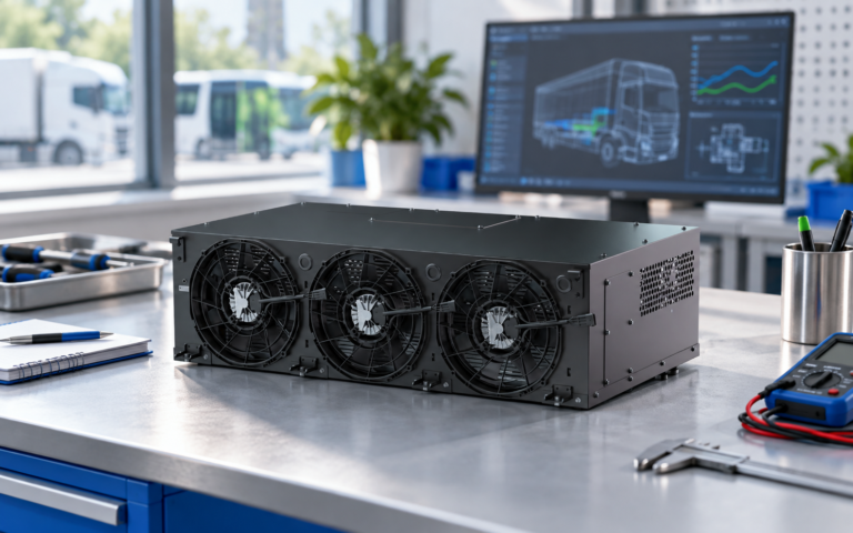
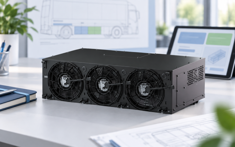
EVLINK’s battery thermal management system range is a starting point for discussing candidate configurations. Send the project requirements for a review of the system boundary and applicable technical documents. Final performance and compatibility depend on the selected configuration and vehicle-level validation.
Frequently asked questions
Can battery capacity alone determine BTMS size?
No. The duty, heat generation, ambient conditions, allowable temperatures and installed circuit all affect the required configuration.
Is a higher pump rating enough to confirm battery cooling?
No. Compare the installed pressure-loss and flow requirements, including each relevant battery branch, and verify the result under agreed operating conditions.
Who defines battery temperature and charging limits?
Use the requirements for the selected battery configuration and agree how the battery management system communicates those limits to the vehicle and thermal-system controls.
Research: https://www.sciencedirect.com/science/article/pii/S0017931018361489 ; https://saemobilus.sae.org/papers/identifying-pressure-drop-heat-transfer-correlations-a-liquid-cooled-lithium-ion-battery-pack-model-electric-vehicles-hot-cold-driving-2026-01-0394 . Research examples are configuration-specific and are not EVLINK test results.