Book Appointment Now


B SERIES · STRAIGHT PIPE · BA/AMPHENOL
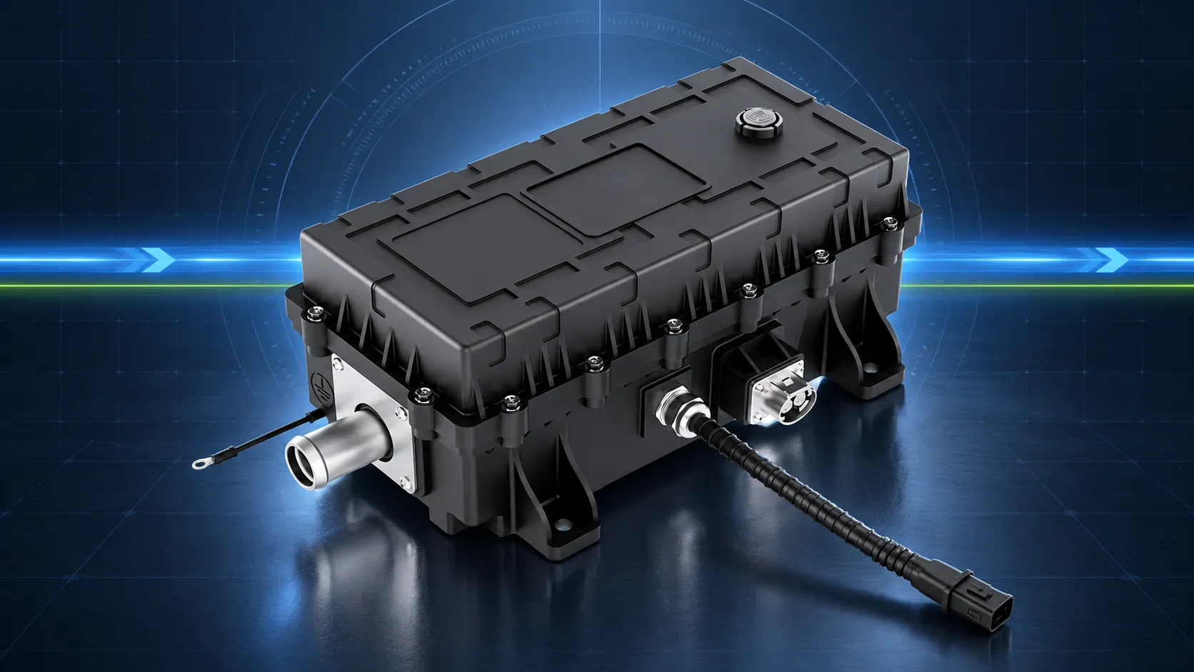
B3 Series 20–24 kW High Voltage Coolant Heater
A wide-range PTC liquid heater for electric bus, truck and off-highway thermal systems—configured around a straight Ø25 mm coolant path and CAN-based vehicle integration.
Selection note: confirm the released voltage, connector, coolant and mechanical configuration for the project variant.
20–24 kW
Published rated-power range
400–800 V
Published operating range
Ø25 mm
Published coolant-port size
IP67
Published ingress protection

WHY B series
A Straight-Path Configuration for Clean Hose Routing
B3 uses a straight coolant-pipe layout. Compare connector, mounting and hose-access requirements with the other B-series configurations before selection.
- Straight Ø25 mm coolant connection shown in supplied material
- 350 × 184 × 120 mm published product envelope
- BA/Amphenol configuration identified by the supplied folder
- 8.5 kg published weight for package planning
ENGINEERING BASELINE
B3 Specifications Grouped by Design Responsibility
Values are transcribed from the supplied B3 artwork. Project-specific limits and tolerances still require controlled documentation.
ELECTRICAL
Power & Voltage
- Rated power: 20–24 kW
- Operating voltage: 400–800 V
- Rated voltage: customizable
- Insulation resistance: ≥100 MΩ at DC1000 V
- Dielectric strength: ≥1200 V
- Peak current: ≤1.5 × rated current
ENVIRONMENT
Thermal & Mechanical
- Operating temperature: −40 °C to +85 °C
- Storage temperature: −40 °C to +85 °C
- Ingress protection: IP67
- Dimensions: 350 × 184 × 120 mm
- Coolant port: Ø25 mm
- Published weight: 8.5 kg
VEHICLE INTERFACE
Control & Protection
- CAN communication with enable control
- PID control and fault self-diagnosis
- Automatic power limiting
- Overvoltage and undervoltage protection
- Overcurrent and short-circuit protection
- Overtemperature protection
INSTALLATION LOGIC
Validate the Straight Coolant Path Before Prototype Freeze
B3 can simplify routing only when hose direction, service access and the vehicle loop are aligned.
01
Place the Heater
Confirm the 350 × 184 × 120 mm envelope, mounting face, orientation and removal space.
02
Align the Liquid Loop
Check in-line hose approach, Ø25 mm interface, flow direction, coolant type, pressure and pressure drop.
03
Close Electrical Access
Reserve connector and harness space; confirm mating parts, keying, HVIL and service reach.
PTC HEATING BEHAVIOR
High-Duty Heating with Built-In Control Functions
The supplied product material highlights high-efficiency heating, rapid heat-up, self-regulating PTC behavior and service-life advantages. For vehicle integration, translate those claims into agreed test conditions, control limits and acceptance criteria.
A
Rapid Heat-Up
Define the heat-up target against coolant flow, inlet temperature and ambient conditions.
B
Automatic Limiting
Align power limiting and derating behavior with the vehicle energy strategy.
C
Fault Diagnostics
Map CAN feedback, fault thresholds and vehicle responses before validation.
D
Protection Coverage
Confirm project thresholds for voltage, current, temperature and short-circuit events.
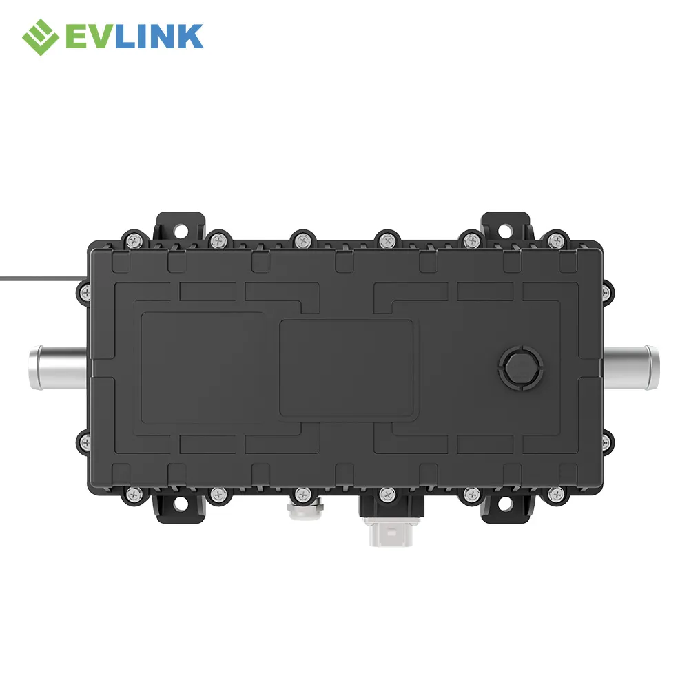
PRODUCT EVIDENCE
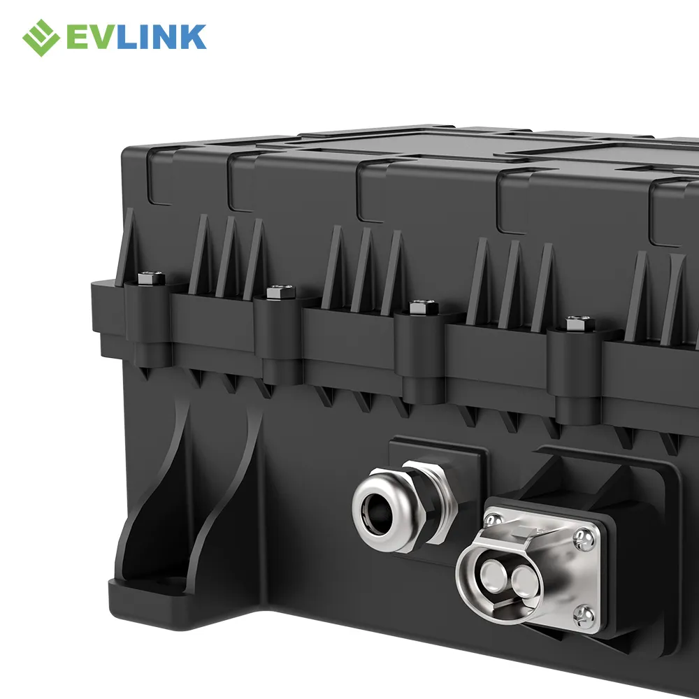
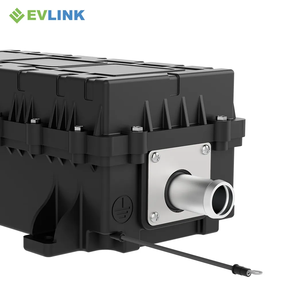
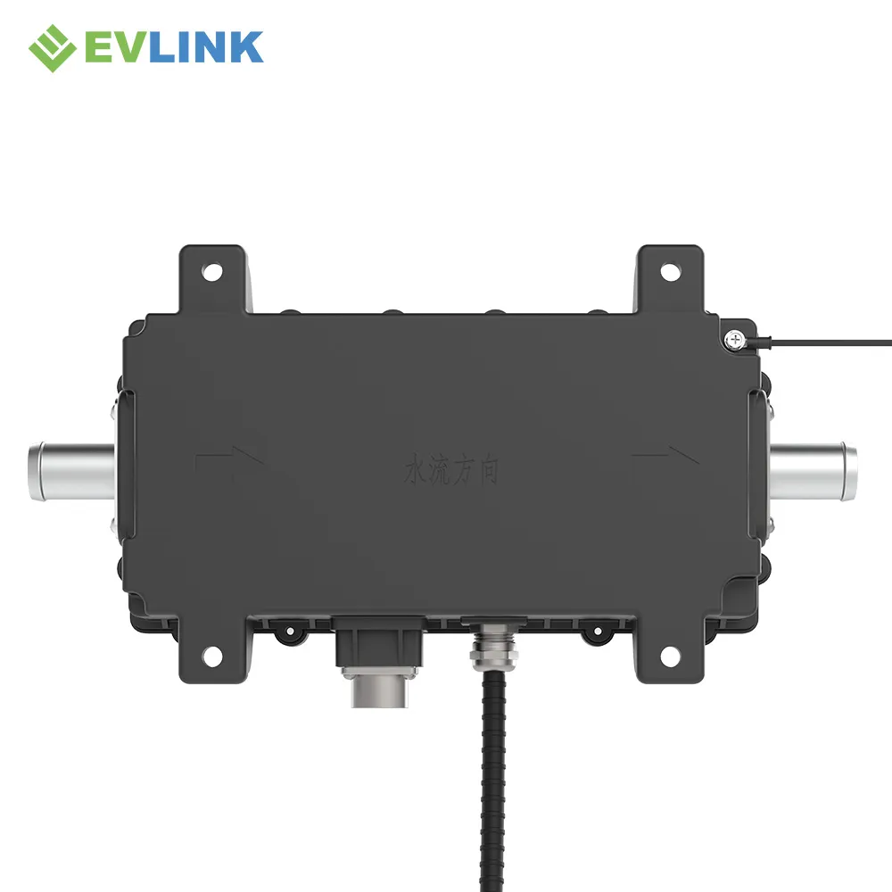
Inspect the B3 Envelope, Ports and Vehicle Interface
Images support orientation review; the released drawing remains the design authority.
VEHICLE APPLICATIONS
Match B3 to the Thermal Duty—not Only the Vehicle Type
The supplied material identifies electric buses, electric trucks and construction machinery as target applications.
BUS
Electric Bus Heating
Evaluate battery preheating, passenger-compartment heat demand, long duty cycles and cold-route conditions.
TRUCK
Electric Truck Heating
Review cab heating, battery temperature strategy, operating schedule and available high-voltage power.
OFF-HIGHWAY
Construction Machinery
Account for harsh ambient exposure, intermittent high load, vibration, contamination and service access.
RFQ PREPARATION
Send Enough Data for a Real B3 Fit Review
A model name alone is not enough to release a heater. Supplying the operating window and package constraints helps engineering return a configuration-focused response.
- Vehicle and heating circuit
- Minimum, nominal and maximum voltage
- Required heat output and warm-up target
- Coolant, flow, inlet temperature and pressure
- Available envelope, orientation and hose direction
- Connector, CAN, validation, timing and forecast volume
B-SERIES MODEL COMPARISON
Compare B1–B5 High Voltage Coolant Heater Configurations
Select by electrical operating range, coolant-pipe layout, low-voltage interface and high-voltage connector family—not by product appearance alone.
01
Confirm Electrical Range
B1–B5 share the supplied 20–24 kW, 400–800 V series range. Select the configuration by connector, coolant-pipe layout, mounting and service access; shared ratings do not make variants interchangeable.
02
Match Coolant Routing
Use the released drawing to confirm pipe direction and hose approach. B2 uses an S-bend layout, while B3 uses a straight-pipe layout.
03
Freeze Connector Family
Confirm the exact HV/LV connector, mating component, pin assignment and harness release before selecting B1, B4 or B5.
B1 SERIES · BA01 / AMPHENOL
B1 High Voltage Coolant Heater
20–24 kW
Rated power
400–800 V
Operating range
Configuration difference
6-pin low-voltage lead · punched LV outlet · PL Ø9
Selection trigger
Choose when the released BA01/Amphenol and 6-pin low-voltage interface match the vehicle harness.

B2 SERIES · BA / AMPHENOL
B2 High Voltage Coolant Heater
20–24 kW
Rated power
400–800 V
Operating range
Configuration difference
S-bend coolant pipe · PL Ø9
Selection trigger
Choose when the vehicle coolant routing requires the supplied S-bend pipe arrangement.
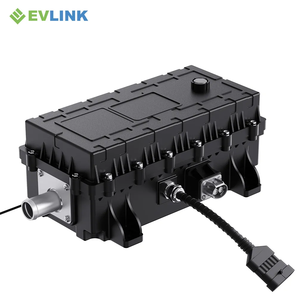
B3 SERIES · BA / AMPHENOL
B3 High Voltage Coolant Heater
20–24 kW
Rated power
400–800 V
Operating range
Configuration difference
Straight coolant pipe · PL Ø9
Selection trigger
Choose for the broader published electrical range and a straight coolant-pipe layout.

B4 SERIES · BG / GUOWEITONG
B4 High Voltage Coolant Heater
20–24 kW
Rated power
400–800 V
Operating range
Configuration difference
BG / Guoweitong socket configuration
Selection trigger
Choose when the approved vehicle-side mating system is based on the BG/Guoweitong socket family.

B5 SERIES · BN / AVIC OPTOELECTRONICS
B5 High Voltage Coolant Heater
20–24 kW
Rated power
400–800 V
Operating range
Configuration difference
BN / 中航光电 socket configuration
Selection trigger
Choose when the released connector and mating components use the BN/中航光电 socket family.
ENGINEERING SELECTION
Not Sure Which B-Series Variant Fits?
Send the voltage window, heating duty, coolant-port direction, released connector family, installation drawing and CAN requirements for a configuration review.
Final configuration check
Before quotation or design release, confirm connector part numbers, mating components, coolant-port geometry, mounting drawing, CAN revision and project-specific electrical limits. Published ranges describe the supplied product material and do not replace the released configuration drawing.
ENGINEERING FAQ
B3 Series Selection Questions
Answers based on the supplied B3 product material, with document-control boundaries stated explicitly.
The supplied B3 material identifies a straight coolant-pipe layout, while B2 uses an S-bend pipe arrangement. B3 also has a different published electrical envelope. Use the released drawings to compare the complete configuration.
The supplied B3 specification shows 20–24 kW rated power and a 400–800 V operating voltage range, with customizable rated voltage. Confirm the released limits for the exact ordered configuration.
The supplied product display states 350 × 184 × 120 mm and Ø25 mm. Confirm tolerances, mounting-hole locations and hose-interface details in the controlled drawing before package release.
The supplied application material positions the heater for electric buses, electric trucks and construction machinery. Final suitability depends on heating load, coolant conditions, voltage window, controls and installation space.
The supplied specification lists CAN communication with enable control, PID control, fault self-diagnosis and automatic power limiting. Request the applicable CAN document and software revision for your project.
Send vehicle type, minimum/nominal/maximum voltage, required heating duty, coolant and flow data, ambient range, available envelope, hose direction, connector requirements, CAN scope, validation standards, timing and forecast volume.
B3 TECHNICAL REVIEW
Is the Straight-Pipe B3 the Right Heater for Your Vehicle?
Send the thermal duty, 400–800 V project window, coolant-loop data, package drawing and communication requirements.
Expected next step
A configuration review covering B3 fit, open engineering points and the documents required before prototype release.