Book Appointment Now


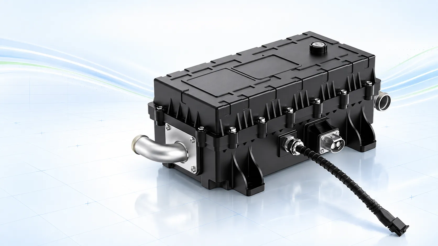
B2 SERIES · BA/AMPHENOL · S-BEND PIPE
B2 Series 20–24 kW High Voltage Coolant Heater
A CAN-controlled PTC coolant heater configured with an S-bend coolant-pipe layout for commercial EV battery and cabin heating circuits.
- 400–800 V published operating range
- S-bend coolant-pipe arrangement · PL Ø9
- BA/Amphenol interface configuration
WHY B series
Designed Around Hose Routing and Interface Fit
B2 should be selected for its physical integration details—not because its headline power and voltage resemble another B-Series variant.
01
S-Bend Pipe Geometry
A curved pipe layout creates a different hose approach from the straight-pipe B3 configuration.
02
BA/Amphenol Interface
The supplied folder identifies the B2 connector configuration as BA/Amphenol; exact parts require drawing confirmation.
03
PL Ø9 Configuration
Use the released interface drawing to confirm dimensions, sealing and hose compatibility.
PRODUCT DESCRIPTION
A Packaging-Led Choice for 20–24 kW EV Heating
The EVLINK B2 Series is a high-voltage PTC coolant heater for liquid-based battery and cabin thermal circuits. The supplied specification lists 20–24 kW rated power, 400–800 V operation, CAN and enable-signal communication, PID control and automatic power limiting. What separates B2 from adjacent B-Series configurations is its BA/Amphenol interface and S-bend coolant-pipe arrangement. That makes B2 a packaging-led choice for projects where hose direction, connector access and service clearance must be resolved together with heating performance.
FIRST-FIT DATA
Can B2 series Fit Your Installation?
- Available envelope and mounting orientation
- Hose approach direction and bend radius
- Mating connector and harness clearance
- Coolant flow direction and pressure limits
- Service and removal clearance
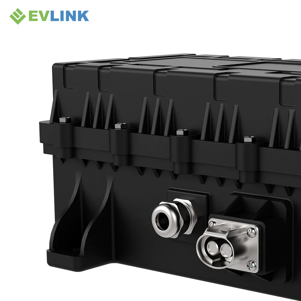
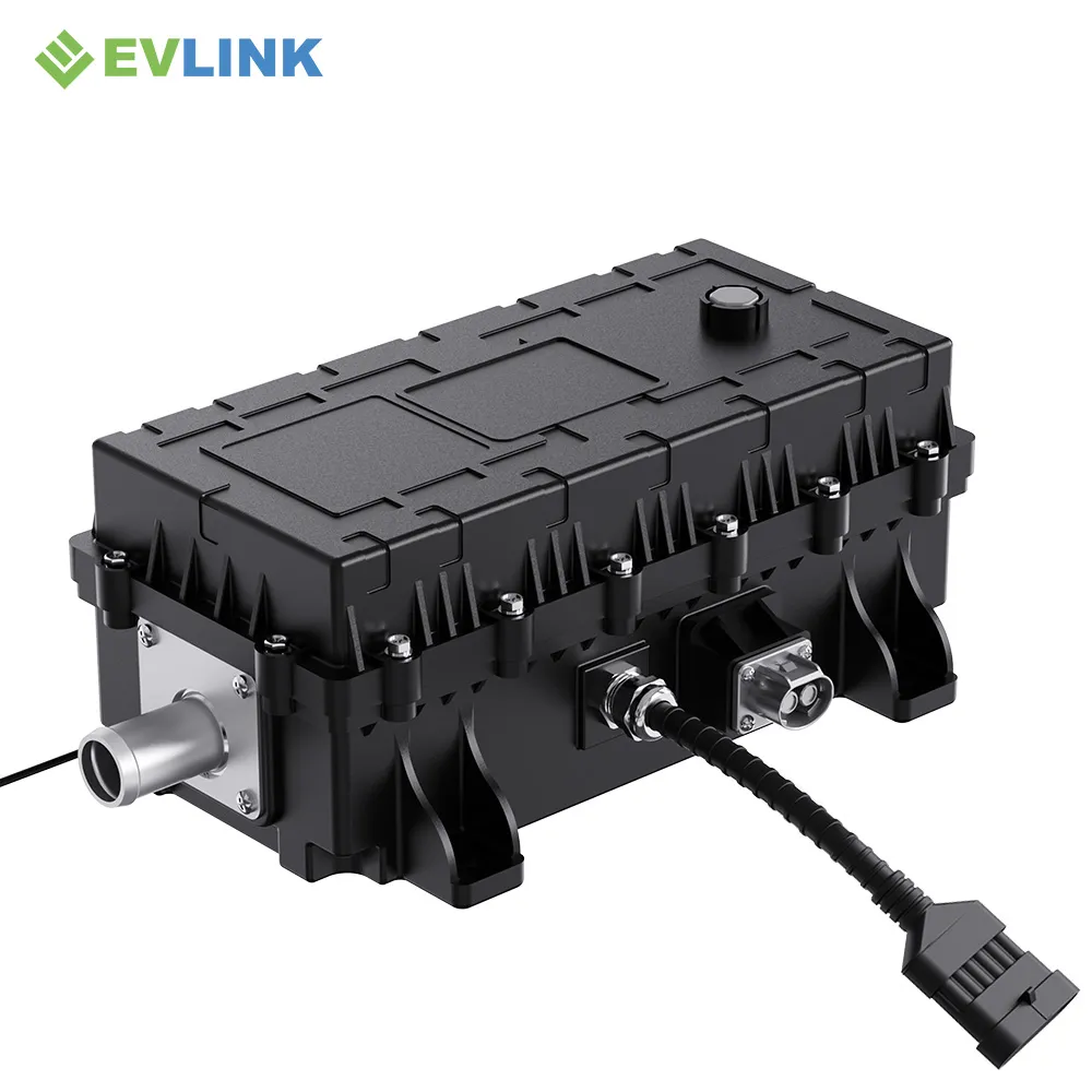
PRODUCT VIEWS
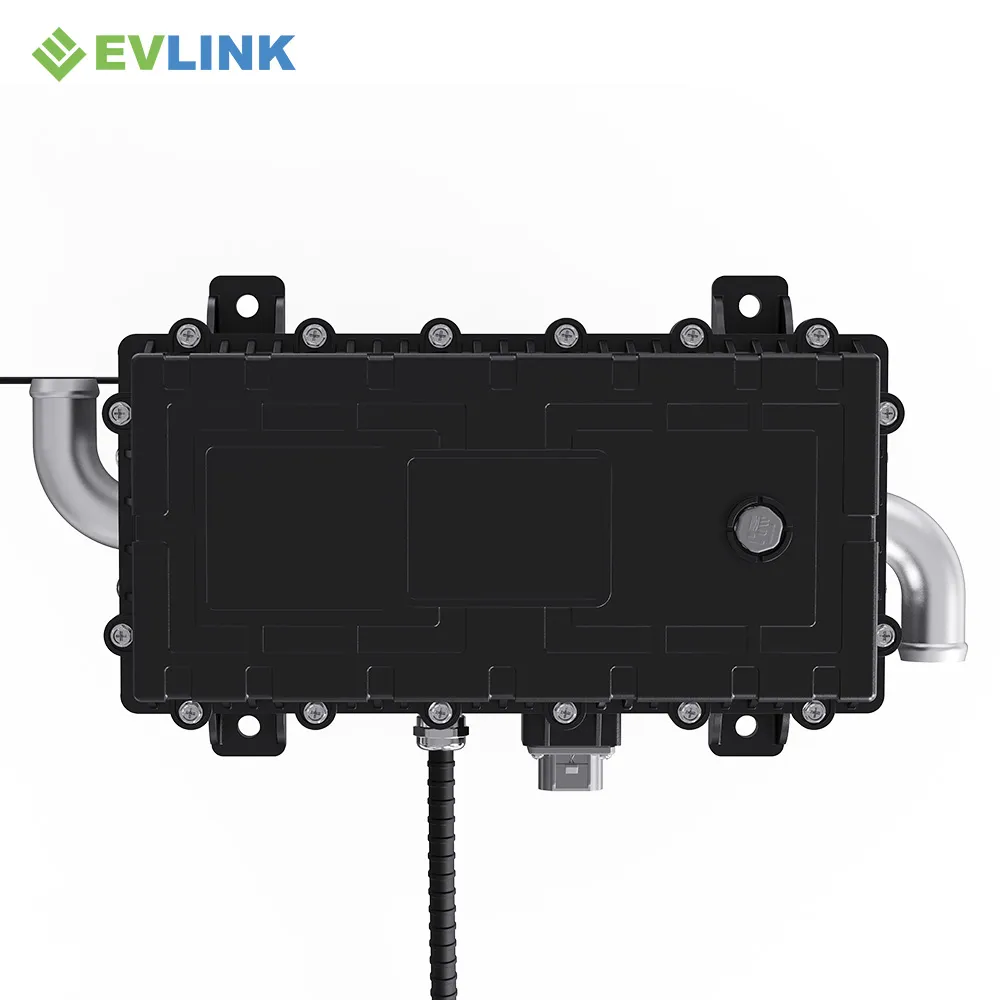
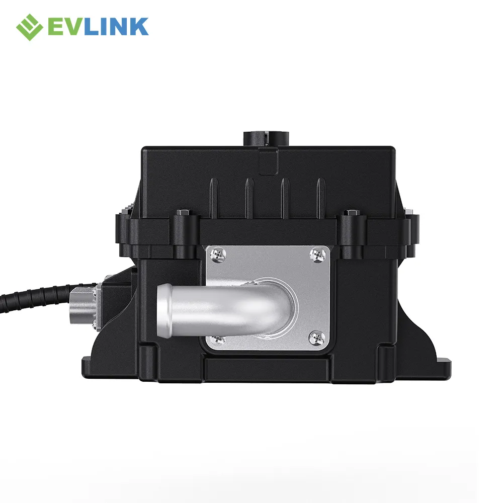
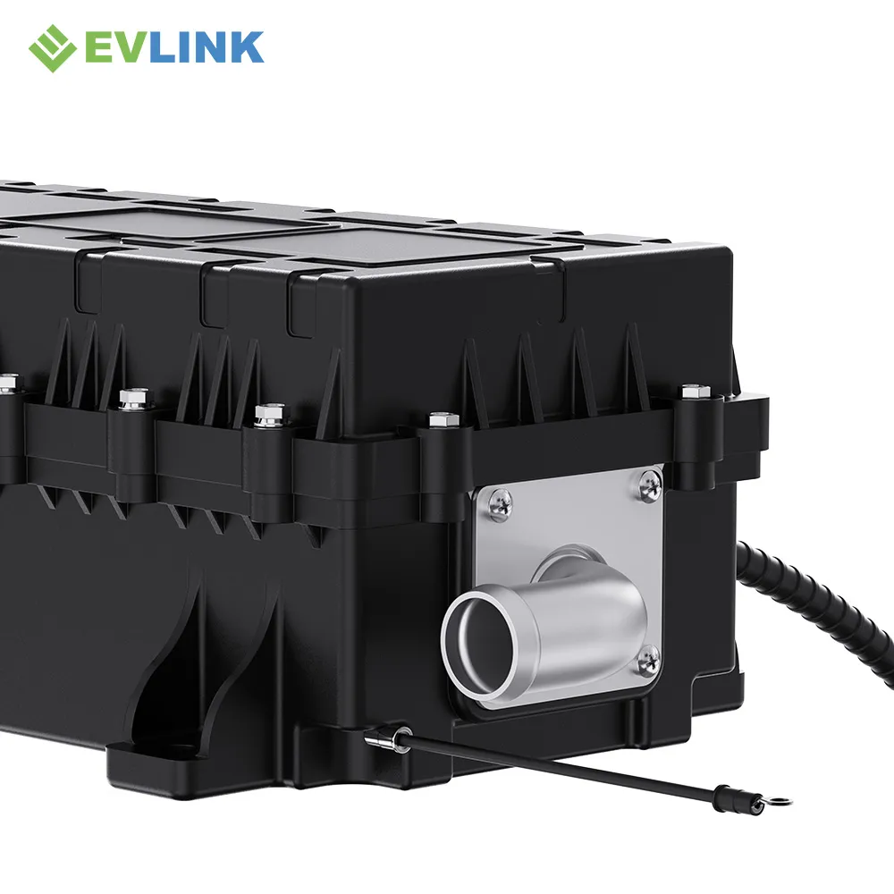
Inspect the B2 series Pipe, Connector and Mounting Layout
Use these views for orientation only. Use the released drawing for design decisions.

TECHNICAL DATA
Specifications Organized for Engineering Review
The values below come from the supplied B2/B-Series artwork. Configuration-specific limits remain part of the project review.
ELECTRICAL & THERMAL
Power and Operating Window
- Rated power: 20–24 kW
- Operating voltage range: 400–800 V
- Rated voltage: customizable
- Operating temperature: −40 °C to +85 °C
- Insulation resistance: ≥100 MΩ at DC1000 V, HV section
CONTROL & PROTECTION
Vehicle Communication and Safety
- CAN and enable-signal communication
- PID control and fault self-diagnosis
- Automatic power limiting
- Over/undervoltage and overcurrent protection
- Short-circuit and overheat protection
- Protection rating: IP67
20–24 kW
Rated power
400–800 V
Operating voltage
8.5 kg
Published weight
2 years
Published warranty
INTEGRATION PATH
Close the Bseries Interfaces Before Prototype Release
A four-step review reduces the risk of choosing a heater that meets power targets but conflicts with the vehicle package.
01
Freeze the Duty
Define battery/cabin load, heat-up target, ambient range and operating priority.
02
Verify the Liquid Loop
Confirm coolant, flow, inlet/outlet conditions, pressure and pressure drop.
03
Close the Package
Check the S-bend pipe, hose approach, bracket, connector and service clearance.
04
Align Vehicle Control
Confirm CAN ownership, commands, feedback, faults, enable logic and validation.
APPLICATION FIT
Where Can Enter the Thermal Architecture
Final suitability depends on heat load, liquid-loop design and package fit.
BATTERY LOOP
Cold-Climate Battery Preheating
Use controlled coolant heating to support cold-start and low-temperature battery operating strategies.
CABIN LOOP
Commercial EV Cabin Heating
Provide electric liquid-loop heat where the vehicle HVAC architecture and heating priority are compatible.
INTEGRATED LOOP
Application-Specific Thermal Circuits
Evaluate combined or auxiliary heating only after pump, valve, flow and control responsibilities are defined.
BUYER CHECKPOINTS
Resolve the Risks Hidden Behind Similar Specifications
Two heater variants may share headline power and voltage while requiring different hoses, connectors, brackets and service space. Purchasing should reference the released configuration—not only “20–24 kW B Series” in the order description.
- Model and drawing revision on quotation and PO
- Exact connector and mating-part definition
- Coolant-port geometry and hose responsibility
- CAN document and software revision
- Test conditions and acceptance limits
- Change-control responsibility
B-SERIES MODEL COMPARISON
Compare B1–B5 High Voltage Coolant Heater Configurations
Select by electrical operating range, coolant-pipe layout, low-voltage interface and high-voltage connector family—not by product appearance alone.
01
Confirm Electrical Range
B1–B5 share the supplied 20–24 kW, 400–800 V series range. Select the configuration by connector, coolant-pipe layout, mounting and service access; shared ratings do not make variants interchangeable.
02
Match Coolant Routing
Use the released drawing to confirm pipe direction and hose approach. B2 uses an S-bend layout, while B3 uses a straight-pipe layout.
03
Freeze Connector Family
Confirm the exact HV/LV connector, mating component, pin assignment and harness release before selecting B1, B4 or B5.
B1 SERIES · BA01 / AMPHENOL
B1 High Voltage Coolant Heater
20–24 kW
Rated power
400–800 V
Operating range
Configuration difference
6-pin low-voltage lead · punched LV outlet · PL Ø9
Selection trigger
Choose when the released BA01/Amphenol and 6-pin low-voltage interface match the vehicle harness.
B2 SERIES · BA / AMPHENOL
B2 High Voltage Coolant Heater
20–24 kW
Rated power
400–800 V
Operating range
Configuration difference
S-bend coolant pipe · PL Ø9
Selection trigger
Choose when the vehicle coolant routing requires the supplied S-bend pipe arrangement.

B3 SERIES · BA / AMPHENOL
B3 High Voltage Coolant Heater
20–24 kW
Rated power
400–800 V
Operating range
Configuration difference
Straight coolant pipe · PL Ø9
Selection trigger
Choose for the broader published electrical range and a straight coolant-pipe layout.

B4 SERIES · BG / GUOWEITONG
B4 High Voltage Coolant Heater
20–24 kW
Rated power
400–800 V
Operating range
Configuration difference
BG / Guoweitong socket configuration
Selection trigger
Choose when the approved vehicle-side mating system is based on the BG/Guoweitong socket family.

B5 SERIES · BN / AVIC OPTOELECTRONICS
B5 High Voltage Coolant Heater
20–24 kW
Rated power
400–800 V
Operating range
Configuration difference
BN / 中航光电 socket configuration
Selection trigger
Choose when the released connector and mating components use the BN/中航光电 socket family.
ENGINEERING SELECTION
Not Sure Which B-Series Variant Fits?
Send the voltage window, heating duty, coolant-port direction, released connector family, installation drawing and CAN requirements for a configuration review.
Final configuration check
Before quotation or design release, confirm connector part numbers, mating components, coolant-port geometry, mounting drawing, CAN revision and project-specific electrical limits. Published ranges describe the supplied product material and do not replace the released configuration drawing.
B2 QUESTIONS
B2 Series Engineering & Buying FAQ
Answers focused on the S-bend pipe and interface configuration.
B is identified in the supplied product material by its BA/Amphenol interface and S-bend coolant-pipe arrangement with PL Ø9. The selection decision should be based on the installation drawing, mating parts and hose-routing space.
An S-bend arrangement may help when the hose approach direction or adjacent package space does not suit a straight pipe. The final decision requires a dimensional review; pipe shape alone does not prove compatibility.
The supplied B-Series specification states a 400–800 V operating range and customizable rated voltage. Confirm the exact minimum, nominal and maximum limits for the released B project configuration.
The source folder identifies a BA/Amphenol configuration. Confirm the exact connector part number, keying, mating connector, pin definition, cable specification and HVIL requirement before design release.
Provide coolant type, flow range, inlet temperature, target outlet temperature, working pressure and allowable pressure drop. These project conditions are needed even though the published page-level power and voltage values are similar to other variants.
Send the vehicle type, voltage window, heating objective, thermal load, coolant conditions, installation envelope, hose direction, connector preference, CAN requirements, validation standards, prototype timing and forecast volume.
B2 PROJECT REVIEW
Confirm the S-Bend Configuration Before You Freeze the Package
Send voltage, heating target, coolant data, available space, hose direction, connector requirements, CAN scope, timing and volume.
You receive
A B2 fit review, open-point checklist and the next technical documents required for selection.