Book Appointment Now


Liquid-cooled versus air-cooled battery systems: Key considerations for original equipment manufacturers (OEM)
Compare battery liquid cooling and air cooling for electric buses and trucks, including thermal loads, heat rejection, installation and OEM validation inputs.
When selecting a liquid-cooled battery solution, the first question that must be clarified—one that cannot be answered by a chiller quotation alone—is: how is heat dissipated from the battery cells, and where is it ultimately discharged? For buses or lorries, every stage of the heat transfer pathway is critical. Even in battery packs utilising liquid cooling systems, the condenser may still rely on external air for heat dissipation.
At EVLINK, we recommend that you clarify the overall system architecture before comparing different pieces of equipment. Otherwise, a situation may arise where two suppliers provide quotations for different parts of the thermal management system, yet both refer to them vaguely as ‘cooling’ systems.
Battery liquid cooling and ‘air-cooled chillers’ are not mutually exclusive concepts
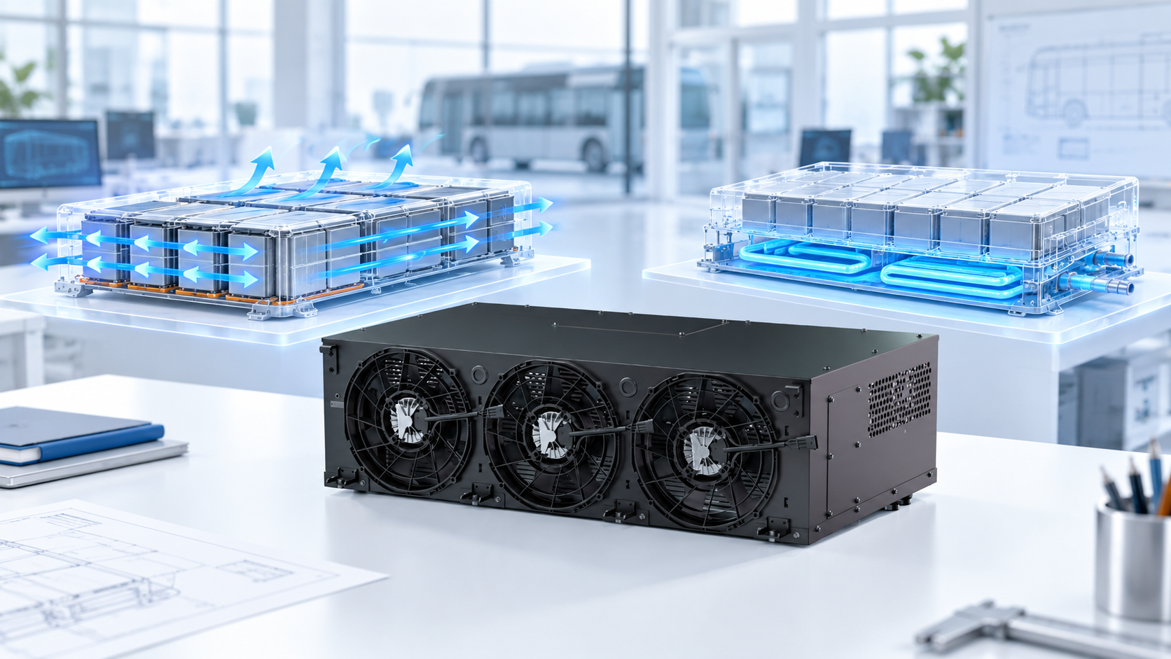
Direct air cooling involves passing air through or around the battery pack to remove heat, whilst indirect liquid cooling utilises a coolant to exchange heat via channels or cold plates thermally connected to the battery cells. These represent two distinct thermal management configurations at the battery pack level.
‘Air-cooled battery chillers’, however, fall into a different category. They cool the battery pack’s liquid-cooling circuit via a refrigerant heat exchanger, whilst utilising a condenser to dissipate heat into the ambient air. Although air is used at the condenser end, the heat within the battery pack is still transferred via the coolant. Therefore, referring to this unit as ‘air-cooled’ does not imply that air flows directly through the interior of the battery pack.
When drawing up technical specifications, it is advisable to first sketch a simple heat transfer path diagram covering: the battery cells, thermal interfaces, coolant, heat exchangers and the final heat dissipation point (radiator/condenser). Our ‘Guide to Refrigerant and Coolant Circuits’ describes this dual-circuit architecture in detail.
When should direct air cooling be considered?
A direct air cooling solution is worth evaluating when the battery pack’s thermal load, permissible temperature range and available air intake conditions are all met. Direct air cooling does not require a coolant circuit within the battery pack, but it does require a clearly defined airflow path, equipped with suitable filtration devices where necessary, and maintenance access routes to facilitate inspection.
Never base your choice of cooling solution solely on the vehicle’s size. A small vehicle that frequently operates at high power levels may actually have more complex thermal management requirements than a large vehicle operating under steady-state conditions. Be sure to confirm with your battery supplier the permissible temperature range and temperature differential limits for the battery cells under your anticipated operating conditions.
Furthermore, the source of the cooling air must be confirmed. If the intake air itself is at a high temperature, its heat dissipation capacity will differ significantly from that achieved with low-temperature intake air. If conditioned air from the passenger compartment (air conditioning) is used, its requirements should be factored into the vehicle’s heating, ventilation and air conditioning (HVAC) assessment, rather than being treated as a ‘free’ cooling resource.
What changes does the selection of a liquid-cooled battery system entail?
Liquid cooling technology provides designers with a predictable heat transfer circuit. At the same time, it introduces a number of interface components requiring specialised design, including cold plates, connectors, seals, pumps, valves, as well as issues relating to coolant compatibility. If the heat transfer path between the battery cells and the coolant is poorly designed, even the most high-performance cooler (chiller unit) will be unable to compensate for this shortcoming.
A comparison of different solutions for the same battery application scenario:
- Consider heat generation over time, including during the charging process and under the most severe typical driving conditions.
- Refer to the permissible temperature range and temperature differential limits set by the battery owner for the battery cells.
- Take into account the available packaging space, power supply and final thermal management conditions.
- Assess the ease of inspection, cleaning, leak management and maintenance over the vehicle’s expected service life.
There are no universal conclusions such as ‘liquid cooling is always cheaper’ or ‘air cooling is always sufficient when the battery pack size is below a certain threshold’. Such judgements must be based on comparative analysis specific to each vehicle model.
Compare actual cooling capacity rather than relying solely on the rated power (in kilowatts) stated in product manuals.
When assessing cooling-side performance, heat transfer is typically calculated based on mass flow rate, specific heat capacity and temperature rise within specific limits: Q̇ = ṁ × cₚ × ΔT. The physical properties of the actual coolant at the relevant temperatures should be used in these calculations. This is merely one calculation method and cannot replace actual measurements of an installed system.
The same rated cooling capacity may correspond to different inlet temperatures, flow rates or environmental conditions. You should request that suppliers provide performance data for your specified operating conditions. If the aim is to compare the energy consumption of the entire system, the electrical loads of pumps and fans must be included within the scope of the comparison.
Please refer to our ‘Cooling Capacity Rating Guide’ for comparative evaluation. During the evaluation process, do not simply regard higher nominal values as an automatic indication of improved performance.
Identify the heat dissipation path within the vehicle
Liquid-cooled circuits are solely responsible for heat transfer; they do not cause heat to vanish into thin air. The performance of radiator-based (heat exchanger) circuits depends on the temperature difference between the system and the ambient air on the cooling side. Refrigerant-based cooling systems (chillers) introduce an additional refrigeration cycle, which incurs extra power requirements and places corresponding demands on the condenser.
For air-cooled condensers, their operating environment in the vehicle’s final assembled state must be assessed, rather than relying solely on their performance in an open workshop environment. Factors such as body panels, surrounding airflow and stationary operating conditions will all alter their operating environment. The assessment of airflow around the condenser encompasses an examination of these installation conditions.
Furthermore, liquid-cooled systems cannot automatically guarantee effective control of ‘thermal runaway’. Conventional temperature management and safety assurance under abnormal operating conditions fall within distinct engineering domains, each requiring its own engineering rationale and a clear definition of respective responsibilities.
Compare service commitments, rather than focusing solely on the hardware itself
Before requesting a quotation, please clarify the operational capabilities the vehicle must possess with the support of the cooling system. Does the vehicle need to commence a new round of high-power charging and return to its operational route, or remain stationary with only limited auxiliary power available? Temperatures achieved on a test bench do not necessarily mean the vehicle is ready for the next phase of operation.
For fleet vehicles, an effective assessment should comprehensively consider the cooling system and the operational constraints it imposes. If a particular solution requires longer downtime (or charging) intervals, this condition must be factored into the assessment. Never regard a lower purchase price as a direct ‘cost saving’ until the operational timetable and charging assumptions are aligned.
A practical comparative analysis of three vehicle operational scenarios
The above content is provided solely as a planning example; it does not represent an EVLINK customer case study, nor does it constitute advice regarding specific battery chemistries.
- Low-demand urban driving conditions: Assess whether the available cooling air can meet the limits set by the battery owner whilst the vehicle is in motion and at a standstill. If there is sufficient evidence, a direct air-cooling solution may still be considered as an option; air-cooling solutions must not be ruled out simply because liquid-cooling solutions are available.
- Frequent ‘opportunistic’ charging: The entire ‘driving–charging’ cycle must be assessed. Record the temperature at the start of each charge, the duration of cooling available, and the state of the battery at the start of the next journey. If the battery is returned to the same initial temperature before each run in laboratory testing, this may mask the heat accumulation that occurs during actual operation.
- High-load conditions in confined installation spaces: Comprehensive consideration must be given to both battery pack-level cooling and vehicle-level heat dissipation. A liquid-cooled battery pack may require a chiller; however, the installation location of the chiller itself must ensure effective heat dissipation under both anticipated stationary and driving conditions.
Ensuring quantifiable thermal performance comparisons
Assuming the fluid flow rate in a cooling circuit is 0.5 kg/s and the specific heat capacity under test conditions is 3.5 kJ/(kg·K), if a temperature rise of 4 K is measured at the defined load boundary, the calculation yields: 0.5 × 3.5 × 4 = 7 kW. The above figures are hypothetical and do not represent product-rated specifications or recommended flow rates.
This calculation reflects the heat transfer across the selected boundary, but it cannot determine the maximum temperature of the battery cells, cannot verify whether all cooling branches have achieved sufficient cooling flow rates, nor does it reflect the electrical power consumed by the entire system. Furthermore, without fluid density data, it is impossible to convert this into a flow rate requirement in ‘litres per minute’. In test reports, it is essential to clearly distinguish between these concepts.
If a supplier reports the heat exchange capacity of their chiller as 7 kW, but the actual measured data on the battery side does not match this, the measurement boundaries, time points and measurement uncertainties should first be verified. Under transient operating conditions, heat stored within the coolant and hardware may cause discrepancies in measurements taken at the same instant. Do not directly attribute such deviations to a chiller fault until these factors have been fully clarified.
Consider scenarios beyond ‘ideal operating conditions’
The requirements under cold start conditions are entirely different from those under summer cooling conditions. If the battery pack requires heating, the permitted charging and discharging conditions must be clarified with the battery owner, and the heat source identified. Simply adding a liquid cooling system does not provide heating functionality. A coolant heater is one of the optional components, depending on the vehicle architecture and electrical budget.
When planning maintenance work, the following aspects should be taken into account: ease of cleaning, requirements for filters (where fitted), coolant replacement instructions, accessibility of connectors, and procedures for responding to cooling system failures. Air-cooled systems are not maintenance-free, and even the use of a sealed liquid circulation system does not mean that inspection can be omitted.
Finally, it is worth asking the supplier: which missing input conditions might lead to changes in the established architectural design? An ideal response should clearly define the decision-making boundaries, such as: insufficient cooling capacity, undetermined battery pack temperature limits, or operating conditions (duty cycles) that exceed the validated range. A mere general assertion that a particular cooling method is ‘always superior’ to others does not truly address any of the above issues.
Input information required for developing a Battery Thermal Management System (BTMS) solution
When conducting an assessment, please provide the following information: the battery pack cooling layout, temperature limits specified by the battery manufacturer, thermal load distribution, coolant requirements (if applicable), and the overall vehicle layout. Furthermore, please take into account any impact that charging while stationary or vehicle idling may have on thermal management requirements.
- Battery-side definitions: These include the battery pack interface, approved temperature limits, and the sources of thermal load data.
- Operating condition sequences: These cover driving, charging, parking and energy recovery phases, and specify the initial conditions and available power.
- Installation requirements: These relate to dimensional specifications, the positions of air inlets and outlets, the distribution of surrounding heat sources, and access routes for maintenance and servicing.
- Acceptance criteria: Define measurement boundaries, readiness requirements upon delivery, and procedures for handling unverified operating conditions.
Please advise us which parameters are fixed and which are adjustable. This will enable us to discuss the required Battery Thermal Management System (BTMS) configuration without having to assume a generic battery pack size or a single cooling metric as the basis for selection. We invite you to share your cooling requirements with EVLINK and to specify the performance data you require to support your decision-making process.