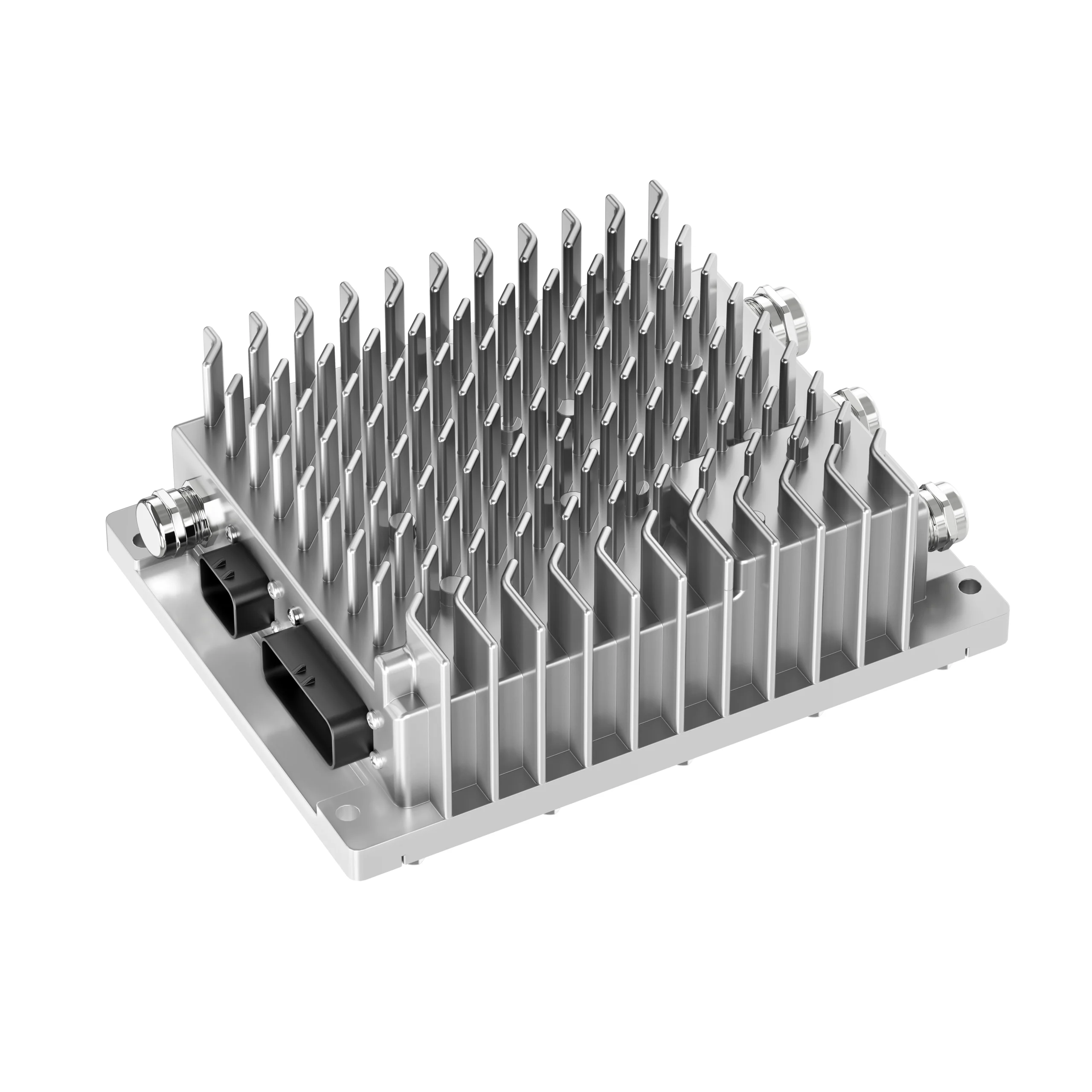
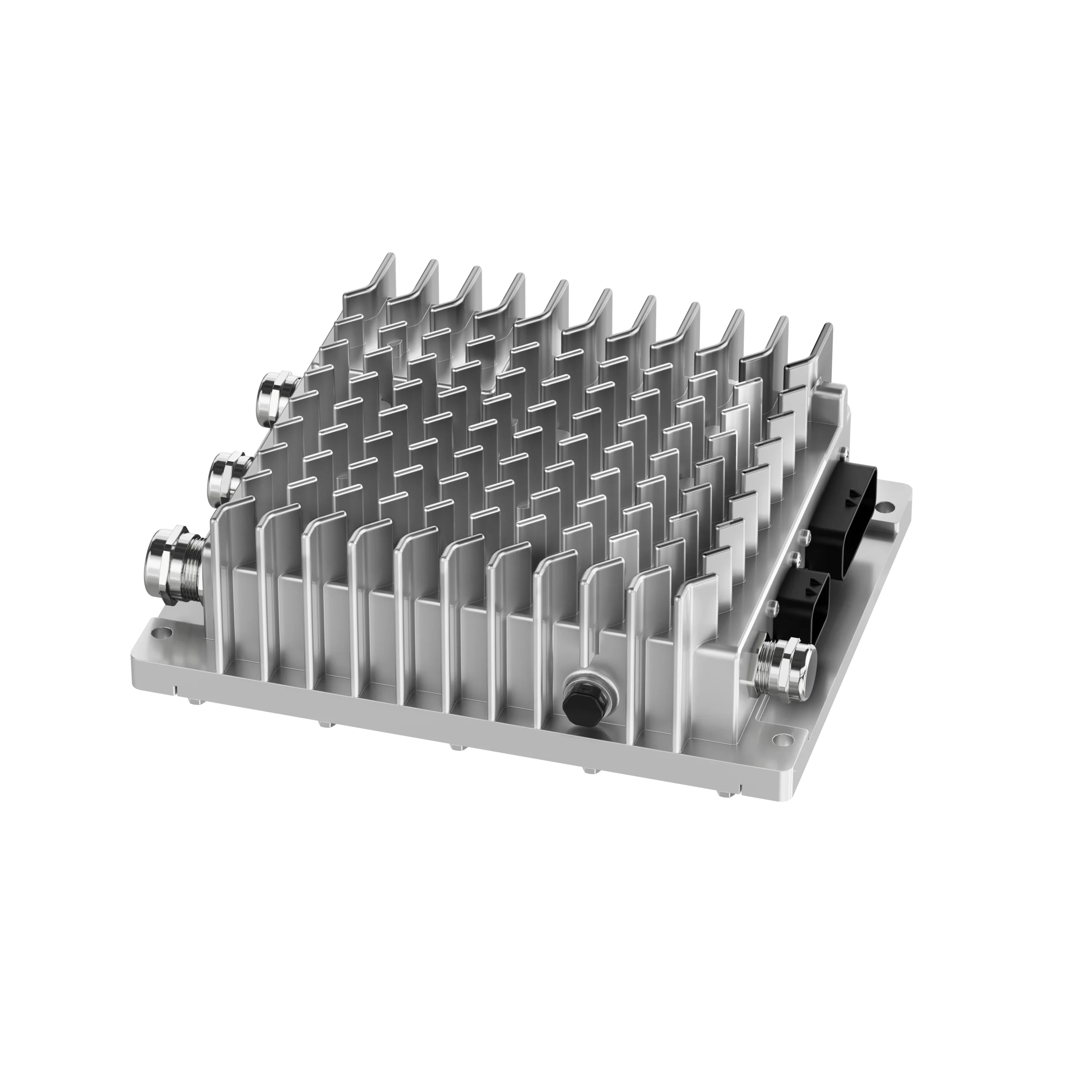
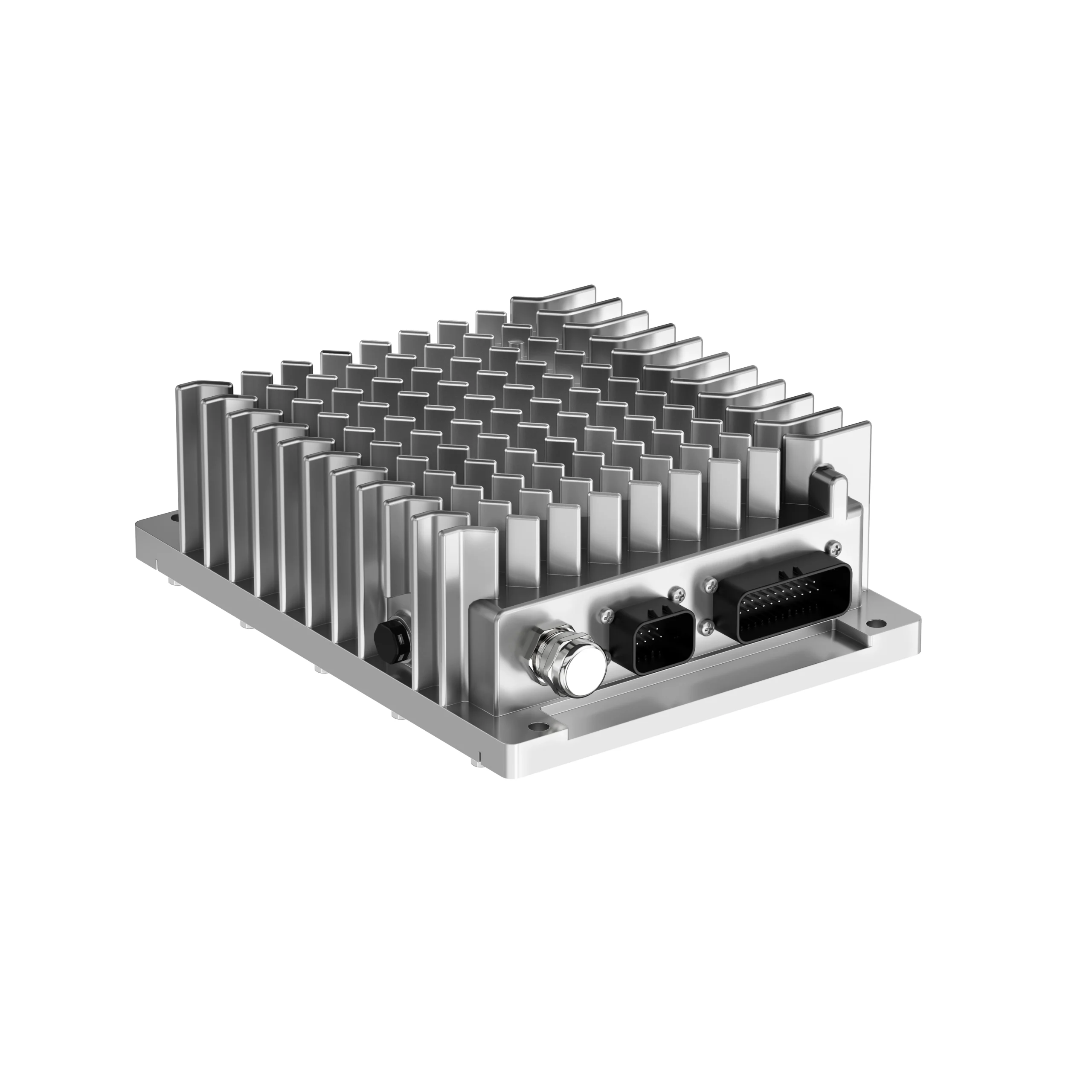
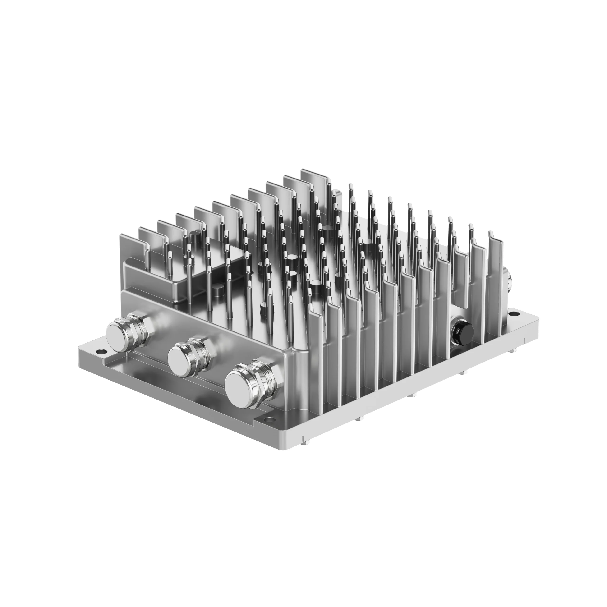
Integrated control for the electric compressor, refrigeration system and high-voltage PTC heater on 600 V and 800 V electric vehicle platforms.
The latest open-fin design combines DCAC compressor control, refrigeration-system ECU functions and high-voltage PTC control with SiC power devices, metal cable glands and natural air cooling.
The integration boundary must be matched to the vehicle electrical architecture, thermal circuit and control responsibility.
01
DCAC Compressor Controller
Controls the electric compressor power stage and coordinates compressor operation with the thermal system strategy.
02
Refrigeration System ECU
Coordinates refrigeration operating modes, vehicle requests, system states, feedback and diagnostic handling.
03
High-Voltage PTC Controller
Controls high-voltage coolant-heater operation within the agreed commands, limits and protection strategy.
Product Views
INTEGRATION CONFIGURATION
How the Three-in-One Controller Fits the Vehicle
High-voltage input, 24 V control power and CAN communication are coordinated with three thermal-control functions.
VEHICLE INPUTS
600 V / 800 V Battery
24 V Low-Voltage Supply
CAN 2.0 Communication
THREE-IN-ONE CONTROLLER
DCAC COMPRESSOR CONTROL
REFRIGERATION SYSTEM ECU
HIGH-VOLTAGE PTC CONTROL
ELECTRIC
COMPRESSOR
REFRIGERATION
SYSTEM
HIGH-VOLTAGE
PTC HEATER
TECHNICAL PERFORMANCE
Parameter Specifications
Values below are based on the product parameter information supplied by EVLINK. Final selection remains configuration- and project-dependent.
Technical Performance
Parameter Specification
Integration Configuration
DCAC compressor controller, refrigeration system ECU and high-voltage PTC controller
Rated DC Voltage
600 V DC or 800 V DC
Controller Input Voltage Range
250–750 V DC (600 V platform); 600–1000 V DC (800 V platform)
Battery Nominal Voltage
600 V DC or 800 V DC
Battery Operating Voltage Range
400–750 V DC (600 V platform); 600–1000 V DC (800 V platform)
Control Box Protection Rating
≥ IP67
Cooling Method
Natural air cooling
Required Cooling Air Speed
≥ 3.5 m/s at the installation area; same airflow speed as the condenser
Communication Protocol
CAN 2.0
Low-Voltage Control Power Supply
24 V DC (16–32 V DC)
Pre-charge Circuit
Integrated pre-charge resistor circuit
Operating Ambient Temperature
−40°C to +65°C
Controller Mass
6 kg (+10% as supplied; tolerance notation requires engineering confirmation)
Mounting Orientation
Vertical mounting; vehicle layout should allow installation, removal and maintenance access
COOLING REQUIREMENT
Natural Air Cooling Requires a Defined Vehicle Air Path
The latest design uses natural air cooling instead of a dedicated controller liquid-cooling connection.
The installation area must provide an air speed of at least 3.5 m/s and the same airflow speed as the condenser. EVLINK engineering should review the real mounting position, ducting, condenser location, surrounding heat sources and service clearances before release.
≥ 3.5 m/s
Required air speed at the controller installation area
Same as Condenser
Airflow condition stated in the latest technical material
LATEST DESIGN ADVANTAGES
Integrated for Commercial-Vehicle BTMS Liquid-Chiller Systems
The supplied material identifies the following design directions. Final cost, EMC, reliability and thermal-performance claims require project evidence before publication.
01
Integrated Architecture
Combines DCAC compressor control, refrigeration ECU and high-voltage PTC control to simplify the system boundary and external connections.
02
SiC Power Devices
The latest design uses SiC power devices as the stated route to higher voltage capability and lower heat generation.
03
Metal Cable Glands
Metal cable-gland connections are used as the stated route to stronger sealing and connection reliability.
04
Natural Air Cooling
Removes the controller liquid-cooling connection, subject to the defined ≥3.5 m/s installation airflow requirement.
05
Compact Vertical Package
The open-fin, vertically mounted package is designed to save installation space and support service access.
06
600 V / 800 V Platforms
Supports two rated vehicle voltage platforms within the listed controller and battery operating ranges.
INTEGRATION REVIEW
Four Interfaces Must Be Confirmed Before Release
A nominal voltage match alone is not sufficient for controller selection.
01
High-Voltage Review
Confirm battery nominal voltage, minimum and maximum operating voltage, current limits, pre-charge strategy, interlock and protection coordination.
02
Low-Voltage & CAN Review
Confirm 24 V supply conditions, wake/sleep behavior, CAN baud rate, messages, states, faults, diagnostics and control ownership.
03
Load & Interface Review
Confirm compressor and PTC electrical requirements, refrigeration-control boundary, connectors, pin assignments and harness responsibility.
04
Installation & Airflow Review
Confirm vertical mounting, envelope, fixing points, ≥3.5 m/s air speed, condenser airflow, ambient temperature, surrounding heat, sealing boundary and service access.
APPLICATION AREAS
Built Around Commercial and Off-Highway EV Integration
Each platform requires a separate review of voltage, loads, control responsibility, packaging and validation.
BTMS Liquid Chiller
Primary integration route shown in the latest material for commercial-vehicle battery thermal management.
Battery nominal, minimum and maximum operating voltage
Electric compressor model and electrical requirements
PTC heater model, voltage, power and control requirements
Refrigeration-system control architecture and ECU boundary
24 V supply, wake/sleep and ignition conditions
CAN database, baud rate, messages and diagnostic requirements
HV/LV connectors, pin assignment and harness responsibility
Installation envelope, vertical mounting and service access
Measured air speed, condenser airflow and surrounding heat sources
Ambient temperature, vibration, ingress and heat-source conditions
Pre-charge, interlock and protection coordination
Prototype quantity, validation plan and project timing
ENGINEERING WORKFLOW
From Vehicle Requirement to Released Controller Configuration
Each step closes a defined integration risk before the next commitment.
01
Requirement Review
Confirm voltage, loads, architecture, interfaces, communication, environment and timing.
02
Configuration Selection
Match the requirement to the 600 V or 800 V route and identify open technical items.
03
Interface Definition
Release the agreed HV/LV, CAN, load, mounting, connector and responsibility boundary.
04
Prototype Integration
Support installation, commissioning, communication checks and issue tracking.
05
Validation & Release
Verify the approved configuration under agreed conditions before production release.
BEFORE QUOTATION OR RELEASE
Project-Specific Items That Still Require Confirmation
These items are intentionally not invented or generalized on this page. They must come from the selected product drawing, datasheet, CAN document and validation record.
Output Ratings
Compressor and PTC output current, power and channel ratings.
Mechanical Data
Envelope dimensions, mounting-hole drawing, mass tolerance, cable-gland definition and connector access.
Electrical Interfaces
Connector part numbers, pinout, interlock and harness definition.
CAN Definition
Baud rate, message IDs, commands, feedback, states, faults and diagnostics.
Protection Strategy
Over/under-voltage, over-current, temperature, isolation and fallback behavior.
Cooling & Validation Evidence
Airflow mapping at the installation point plus applicable EMC, insulation, vibration, environmental and customer-specific test records.
FREQUENTLY ASKED QUESTIONS
Three-in-One Controller FAQ
Technical answers should always be read together with the selected configuration and released project documentation.
What functions are integrated into the three-in-one controller?+
It integrates the DCAC compressor controller, refrigeration system ECU and high-voltage PTC controller in one compact control unit.
Why does the latest design use SiC power devices?+
The supplied technical material identifies SiC as the power-device route intended to increase voltage capability and reduce heat generation. Final device configuration and performance evidence remain project-specific.
What airflow is required for natural cooling?+
The installation area requires an air speed of at least 3.5 m/s and the same airflow speed as the condenser. This condition must be checked in the real vehicle air path.
Why are metal cable glands used?+
The latest material identifies metal cable glands as the connection route intended to improve sealing and connection reliability. Final gland, cable and installation details must follow the released drawing.
Which high-voltage platforms are supported?+
The supplied specification covers 600 V DC and 800 V DC nominal platforms. The applicable input and battery operating ranges must be matched to the selected configuration.
Where is this controller intended to be used?+
The latest source positions it for commercial-vehicle BTMS liquid-chiller systems, subject to confirmation of voltage, compressor, PTC, CAN, airflow, mounting and validation requirements.
RELATED PRODUCTS
Complete the Thermal Management Architecture
Connect controller selection with the actual compressor, PTC heater and battery thermal-management requirements.
High Voltage Coolant Heater
Review heater voltage, power, coolant and control requirements.
Define the Right Three-in-One Controller Configuration
Share the battery voltage window, compressor and PTC requirements, refrigeration-control architecture, CAN information, installation space and validation plan.