Book Appointment Now


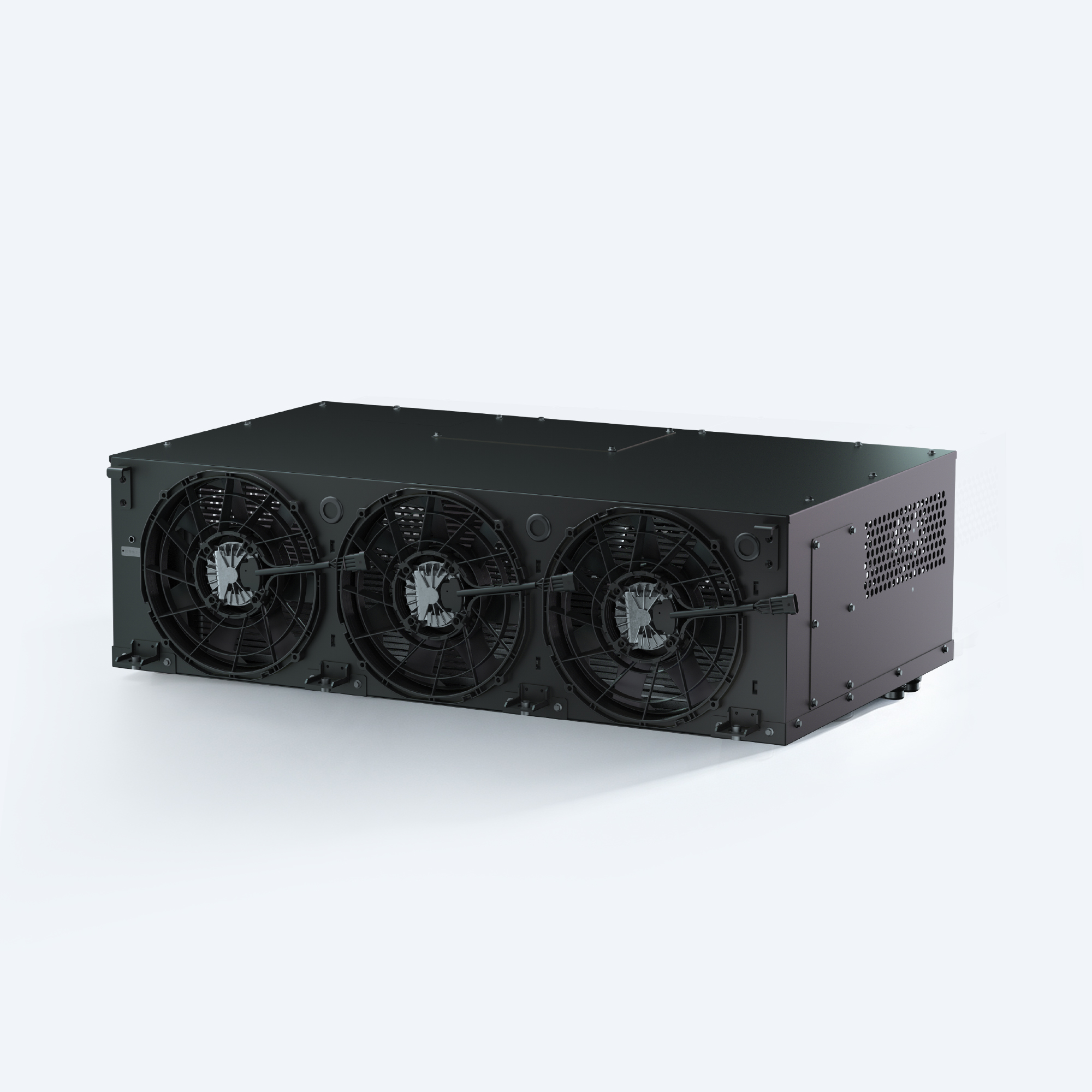
Changes to the Battery Thermal Management System: What Should the Electric Bus Team Re-verify?
A practical guide to reviewing coolant, pump, battery, software and installation changes in an electric bus battery thermal management system.
The Battery Thermal Management System (BTMS) forms part of a specific vehicle configuration and has been validated for that configuration. When changes are made to the coolant, water pump, battery pack, pipework or controller software, previously approved assessment results may no longer apply to the new system configuration. In practice, it is not merely a question of whether replacement components can be fitted, but rather which operating conditions and interfaces require re-verification.
This guide is intended to assist bus and lorry operations teams in carrying out change assessments. It does not set a standard retesting cycle, nor does it replace the specific requirements of battery suppliers, component technical documentation or vehicle-level certification processes.
Starting from the Approved Configuration
Before assessing proposed changes, the baseline status must first be established. This includes: vehicle and battery configuration, BTMS model and version, coolant formulation and concentration, hose and valve layout, power supply system, controller software, and the test records previously used for certification. Please record in detail the nature of the changes, the reasons for them, the implementation date, and any vehicles or configuration versions that may be affected.
Even if the nominal parameters of components are identical, their interfaces or operational characteristics may differ. Please consult the relevant suppliers to confirm the drawings, performance data and usage restrictions applicable to the new version of the component. If the baseline information or newly obtained information is incomplete, mark the relevant decision as ‘pending’; under no circumstances should assumptions be treated directly as accepted facts.
Follow the change across the system
| Change | Questions for the review team |
|---|---|
| Coolant formulation or concentration | Do the approved material compatibility, dilution, hydraulic and thermal data still apply? What cleaning and changeover process is approved? |
| Pump, hoses or valves | What changes to the installed pressure-loss curve and flow distribution must be assessed across relevant operating modes? |
| Battery pack or cold plate | Have heat load, coolant connections, branch flow, temperature measurement or acceptance criteria changed? |
| Controller or software | Are commands, feedback, diagnostic signals, operating limits and mode transitions still compatible with the vehicle? |
| Installation or vehicle structure | Are airflow, service access, routing, mounting and electrical connections still within the agreed installation boundaries? |
These are merely evaluation guidelines; they do not imply that every change requires the same testing. The project team and the supplier should jointly agree on the scope of the evaluation based on the actual changes and their potential impact.
Distinguishing between ‘data transfer’ and ‘validation’
An engineering study on the cooling circuit of an electric bus indicated that the evaluation must cover the entire installed system: differences in circuit pressure loss can affect the distribution of coolant between battery packs. This study focused on a specific vehicle model; therefore, performance under EVLINK configurations cannot be directly inferred. (Please refer to the SAE study summary.)
Data provided by suppliers may serve as a reference for engineering evaluation; however, any curves or reports cited must correspond exactly to the actual hardware, fluids, temperatures and control settings. For example, a water pump performance curve alone cannot determine the actual flow rates in each battery branch once the vehicle’s cooling circuit has been fully installed. Supplier data should be compared against the actual circuit layout; if there are discrepancies in operating conditions, supplementary assessments must be carried out.
For sensor or software changes, the following should be clearly documented: which controller is responsible for each signal; what types of requests are considered valid; and what feedback is used to confirm the actual status. Unless written confirmation of the interface has been obtained, it must not be assumed that the new software version retains all the original control functions.
Develop a targeted validation plan
Prior to testing, list the affected operating modes and clearly define the initial conditions, measurement parameters and acceptance criteria. Depending on the nature of the changes, the scope of assessment may cover: coolant flow rate and temperature, relevant battery sensor readings, the status of pumps and valves, controller requests and feedback, available power, and documented limitations. Standardise the time reference so that the team can compare events across controllers.
Vehicle systems have varying requirements under different operating conditions, such as cold starts, charging or high-load driving. Relevant test conditions should be selected based on the actual changes and the vehicle’s operating conditions. If test results deviate from established benchmark values, the measurement conditions and the modified interface must be verified before attributing the cause to a specific component. It is essential to adhere to established electrical and fluid handling specifications; under no circumstances should any protective functions be bypassed in order to obtain the expected results.
Ensure that the procurement and engineering departments maintain a consistent record of decisions.
A concise change log should clearly specify the following: the affected part numbers and versions, the technical rationale for the change, data provided by all parties, required tests, acceptance criteria, outstanding risks, and the person responsible for issuing the change. Where there are discrepancies between the production configuration and the service configuration, these should be noted separately to enable the maintenance team to clearly identify which approved parts and fluids are to be used.
Conduct a Battery Thermal Management System (BTMS) assessment in collaboration with EVLINK.
Share the current system configuration, battery supplier requirements, relevant operating modes, proposed changes, and existing drawings or test data. Clarify matters requiring decision, such as whether a particular component can be replaced, which interfaces must be updated, or which aspects of the vehicle still require validation.
When carrying out the relevant planning, please refer to the ‘Battery Cold Plate Interface Guide’, the ‘BTMS CAN Integration Checklist’ and the ‘Scope of Quotation Guide’. Before approving any changes, please ensure that the proposed configuration is discussed with EVLINK.