Book Appointment Now



Multiple High-Voltage Coolant Heaters: Plan the Power Budget First
Review power budgets, control coordination and coolant routing when considering multiple high-voltage coolant heaters for electric buses and trucks.
Installing two high-voltage coolant heaters does not automatically double the effective heating capacity. The vehicle must be capable of supplying sufficient electrical power, distributing the coolant appropriately, and coordinating the operation of both units under the selected operating conditions. Before adding a second heater, it is essential to clarify the overall heating requirements and the maximum electrical load permitted by the vehicle.
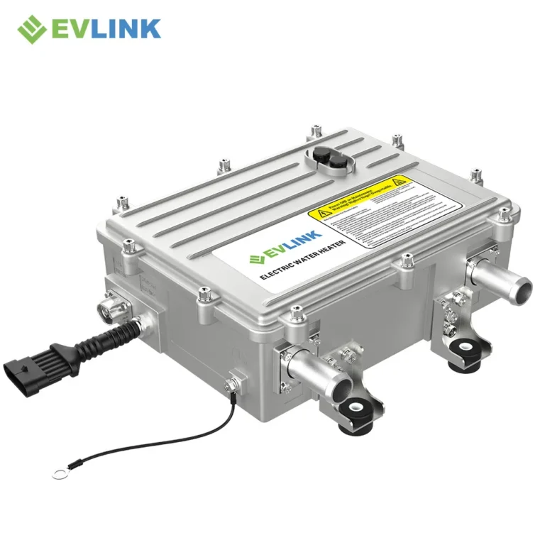
This article aims to explore the system architecture of electric buses and lorries. This article does not confirm whether specific EVLINK heaters support multi-unit configurations; this requires agreement on the selected hardware, software and vehicle interfaces.
Distinguishing between ‘Installed Capacity’ and ‘Available Power’
‘Installed capacity’ refers to the total capacity of the heating equipment actually installed on the vehicle; ‘available power’, on the other hand, depends on the electrical power the vehicle can supply at any given moment, as well as the actual power output of each heater under specified operating conditions.
The available power budget may vary under different operating conditions—such as whilst the vehicle is in motion, charging or preheating whilst parked—and must be shared with other electrical loads. Please consult the vehicle’s electrical team to clarify the maximum power consumption limits permitted for heaters under each operating condition and to confirm whether any time-based restrictions apply.
Never assume that the rated parameters on the nameplate apply across the entire voltage range. Be sure to obtain the operating limitations and performance parameters for the selected heaters. Power and control parameters listed in technical specifications published by other manufacturers apply only to their specific configuration schemes and cannot be used directly as a basis for evaluating EVLINK’s performance.
Clarify the rationale for using multiple heaters
The use of multiple heaters may be driven by considerations such as zoned heating, installation space constraints or tiered power output. These represent distinct design objectives and therefore require corresponding acceptance criteria to be established.
If the aim is to heat the battery and the passenger compartment separately, the specific temperature requirements and timing for each heating target must be clearly defined; if the aim is to achieve graduated power output, it must be clarified how the vehicle allocates the overall heating demand; if the aim is to maintain operation in the event of a fault in one of the heaters, the functional scope of the remaining equipment must be clearly defined and verified through authoritative validation procedures. Merely ‘configuring two heaters’ does not in itself constitute system redundancy.
Before finalising the system architecture, please compare the ‘multi-heater solution’ with the ‘single, appropriately configured heater solution’. Whilst considering equipment costs, a comprehensive assessment must also be made of interface design, installation methods, coolant piping layout, validation work and the ease of subsequent maintenance.
Agree on the method for allocating requests
Identify the ‘responsible party’ for determining the total heating demand (i.e. the unit responsible for allocating the demand). Subsequently, clarify how requests are to be allocated to individual heaters, and how actual operating status is to be reported. Coordinated control cannot be achieved by simply sharing the CAN bus alone.
Document each unit’s identifier, communication requirements, permitted commands and how feedback information is to be interpreted. Confirm that the selected protocol and software support the intended system architecture. Never assume that units of the same model can be connected directly whilst retaining their original identifiers.
The system must be capable of distinguishing between ‘requested power’, ‘reported electrical input power’ and ‘effective heat transferred to the coolant’. If one unit is restricted, never assume that another unit will automatically take on the remaining load demand—unless an approved control scheme and available power permit this.
Assess the coolant circuit layout separately
‘Electrical load distribution’ and ‘hydraulic connections’ are distinct decision-making areas. When using parallel cooling circuits, the flow rate in each branch must be assessed; when using series cooling circuits, downstream units are affected by upstream outlet conditions, and pressure losses occur across components along the entire flow path.
Both configurations have their advantages and disadvantages; there is no absolute superior or inferior option. Please consult the suppliers of heaters and pumps to evaluate the proposed circuit, taking into account factors such as fluid characteristics, valve positioning and operating temperatures. The total pump flow rate does not guarantee that the flow through each branch of a parallel heater circuit will meet expectations.
When deciding between ‘shared’ and ‘independent’ load circuits, please refer to existing guidelines on ‘battery and cabin circuits’. The focus of this assessment is on how to coordinate the operation of multiple heating units within a given system architecture.
Establishing power records for different modes
| Review item | What the project must establish |
|---|---|
| Total heating task | Consumer demand, initial conditions and required duration |
| Supply budget | Available electrical power in each vehicle mode |
| Unit allocation | Individual requests, limits and actual feedback |
| Fluid conditions | Flow and inlet temperature at each heater |
| Communication | Unit identity, signal ownership and validity requirements |
| Restricted operation | Approved response when a unit or supply is unavailable |
| Acceptance | Vehicle-level criteria and the configuration being tested |
Under no circumstances should the maximum rated power of each heater be simply added together and regarded as the approved system output. The actual effective output should be the amount of heat that the system is capable of providing under specified operating conditions and in compliance with the electrical and thermal installation limitations.
It is essential to assess both steady-state operation and the transition between operating conditions.
A validation programme should be developed and approved, covering start-up, changes in demand, mode switching and shutdown. Record vehicle power allocations, demand commands for each heater, feedback signals, coolant status and temperature data for relevant heat-consuming components on a unified timeline.
Testing should only be conducted whilst the dual-heater system is operating stably; this does not reflect the system’s actual performance upon completion of charging or when the vehicle changes modes. Furthermore, the transmission of a control command does not necessarily mean that the system has achieved the corresponding output.
When conducting fault injection tests, authorised specific operating procedures must be strictly followed. This document does not recommend that technicians arbitrarily disconnect live power supplies, disconnect operating equipment, or disable any protective functions.
Provide EVLINK with a complete heating requirements specification.
This should include: the number of heaters to be used, the voltage range, power budgets for each mode, specific requirements for heat-consuming components, and the coolant circuit design. Furthermore, the control architecture must be described, and the rationale for selecting a multi-heater solution must be explained.
Before placing an order, please ensure you confirm with EVLINK that the selected configuration and interfaces are suitable. Whilst the Q Series products may be included in the selection discussion, the overall power coverage of this series does not constitute endorsement of a specific multi-heater system solution. The final solution should clearly specify the verified functional capabilities and list the test items that still need to be carried out on the vehicle side.