K SERIES · DUAL FLYING-LEAD ARCHITECTURE

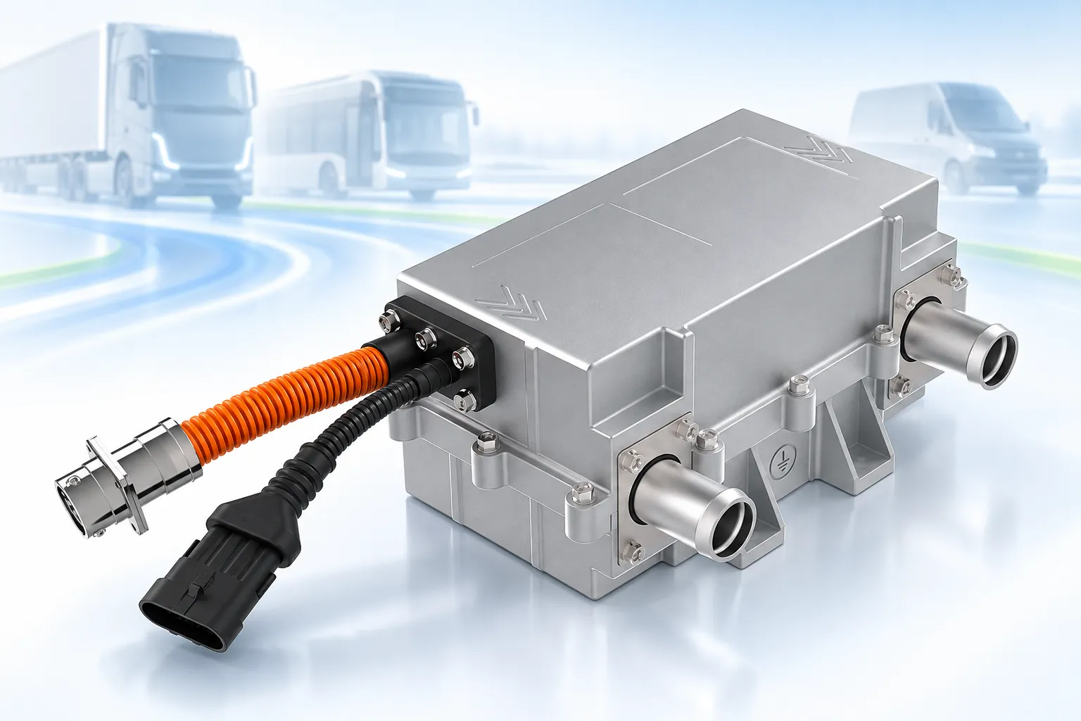
K Series 2–12 kW High Voltage Coolant Heater with HV and LV Flying Leads

A compact PTC liquid-heater configuration for electric commercial-vehicle and off-highway programs that want both electrical interfaces supplied as cable assemblies.

Freeze the high-voltage pigtail, low-voltage control lead, coolant circuit and mounting envelope as one project release.

High Voltage Coolant Heater
2–12 kW

Technical-panel rated power

200–800 V

Published operating range

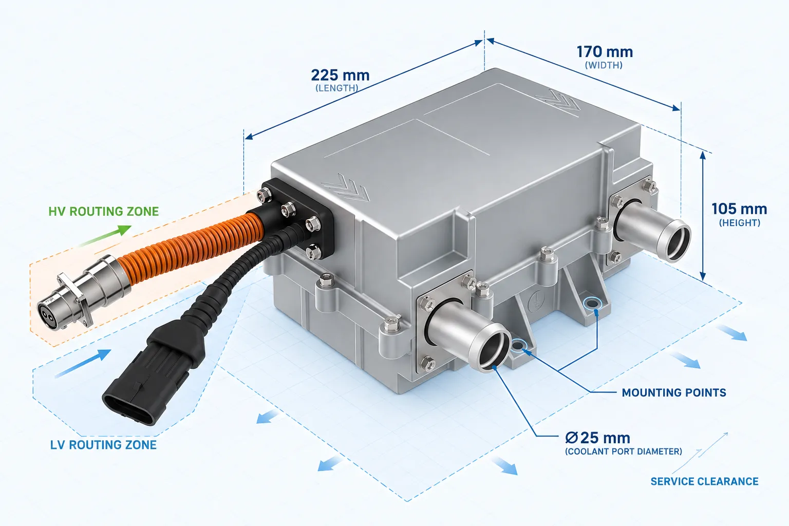
225 × 170 × 105 mm

Published product envelope

Ø25 mm

Published coolant-port reference

High Voltage Coolant Heater
DUAL-LEAD BOUNDARY

Release Two Cable Assemblies, Not Just One Heater

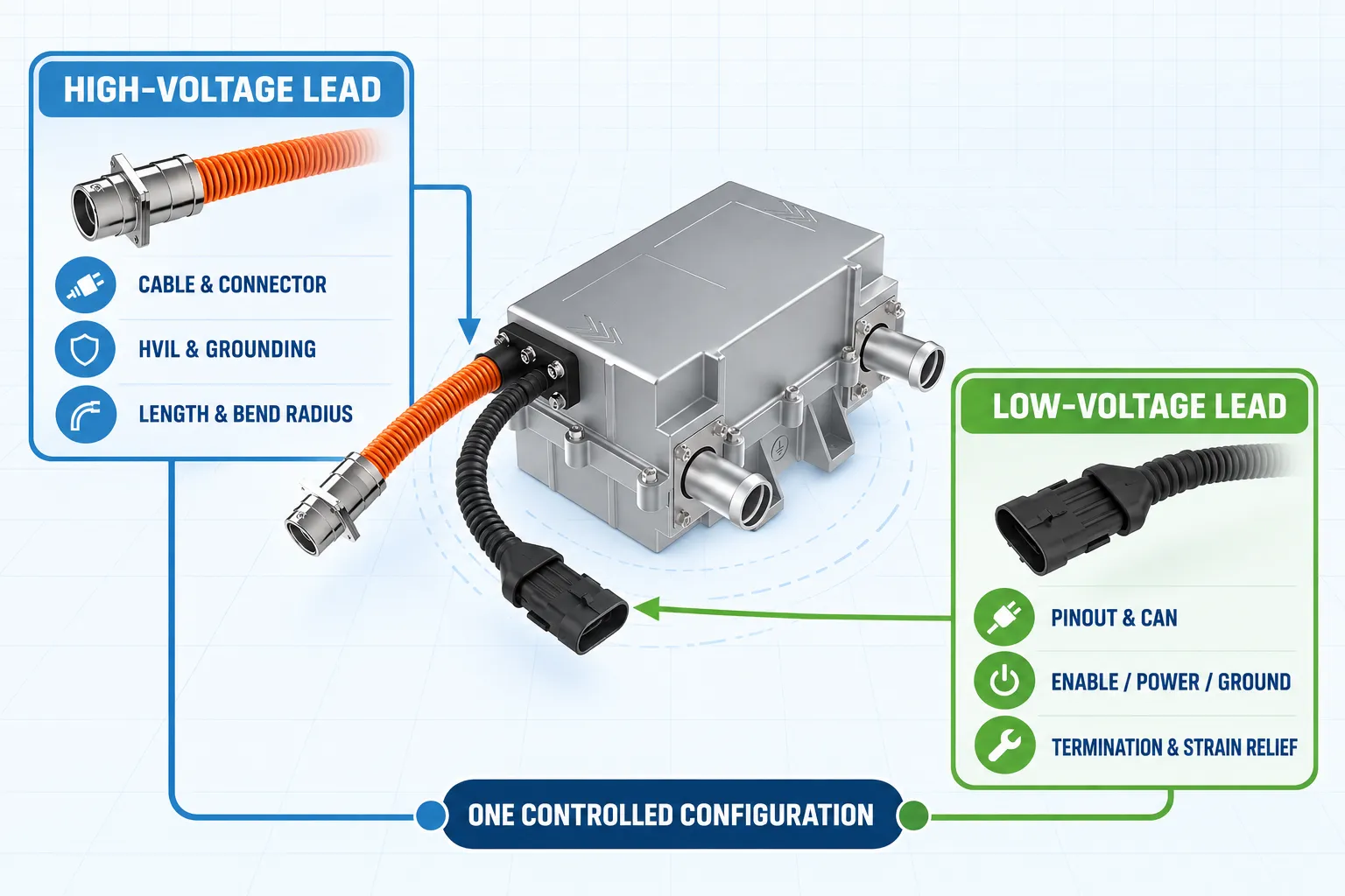
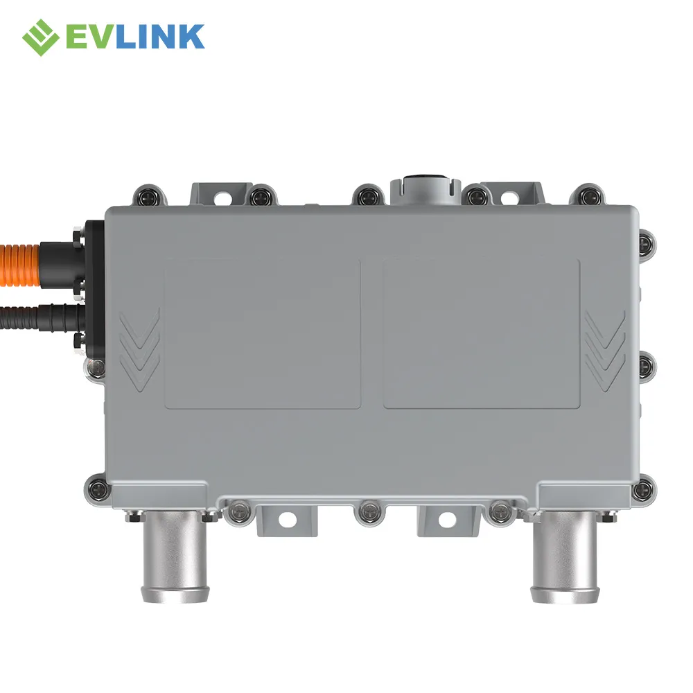
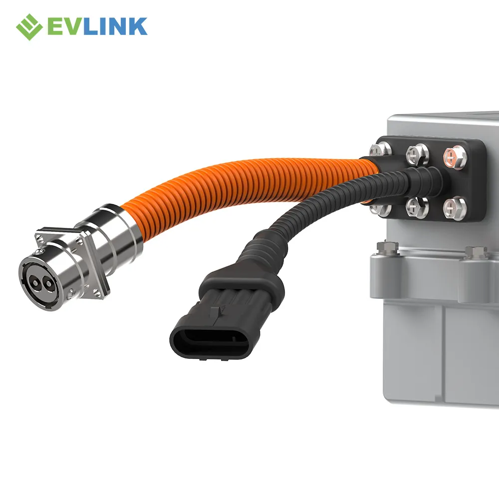
The supplied product views show an orange high-voltage pigtail and a black low-voltage pigtail. Their exact parts and electrical definitions are not stated in the artwork, so both must be controlled with the heater configuration.

HV

High-Voltage Lead

Confirm cable construction, length, connector, mating part, keying, HVIL, grounding and service bend radius.

LV

Low-Voltage Lead

Confirm conductor count, gauge, pinout, CAN, enable, power, ground, termination and strain relief.

MECHANICAL PACKAGE

Use the Short Aluminum Housing as the Packaging Baseline

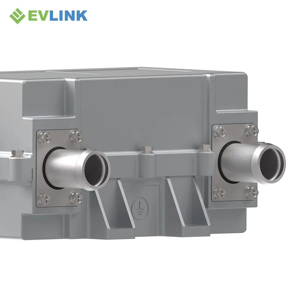
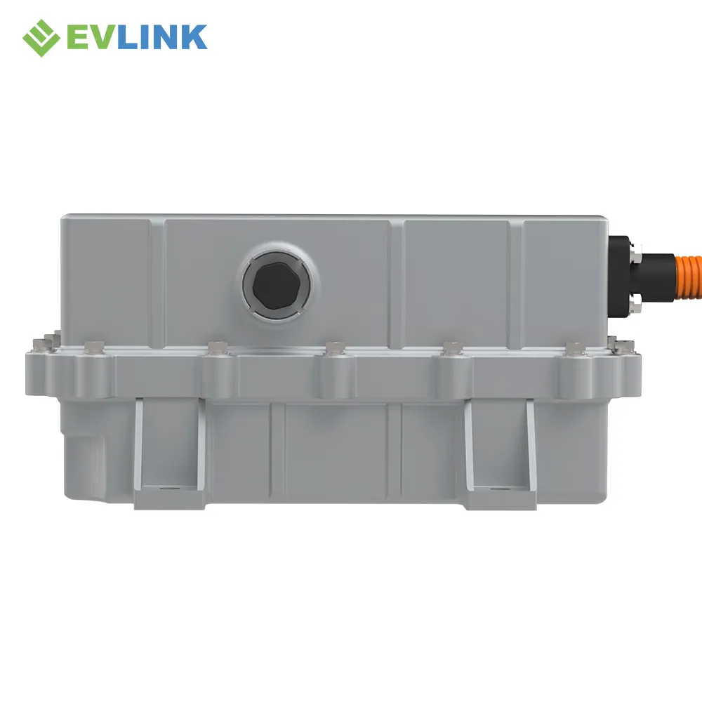
The K-Series enclosure and two opposed coolant ports create a different installation problem from the taller black-housing families.

High Voltage Coolant Heater

Packaging checks

RELEASE SEQUENCE

Freeze the Interfaces in the Order the Vehicle Team Uses Them

Treat the product as an integrated thermal and electrical assembly.

01

Heat Duty

Set coolant, flow, inlet and outlet temperatures, target heat-up time and pressure limits.

02

HV Assembly

Freeze voltage window, cable, connector, HVIL, current limits, insulation and grounding.

03

LV Assembly

Freeze pinout, CAN, enable, feedback, diagnostics, termination and vehicle-harness ownership.

04

Package

Freeze ports, hose routing, mounting, cable clips, drainage, vibration and service access.

TECHNICAL DATA

K-Series Published Specification Baseline

The K-series range is 2–12 kW at 200–800 V DC. Confirm the ordered power, rated voltage and rating conditions for the selected configuration.

Rated Power

The K-series range is 2–12 kW at 200–800 V DC. Confirm the ordered power, rated voltage and rating conditions for the selected configuration.

Rated Voltage

Customizable — confirm the released project configuration

Operating Voltage Range

200–800 V

Product Size

225 × 170 × 105 mm in the supplied product display

Coolant Port

Ø25 mm shown in the supplied product display

Weight

4.3 kg

Insulation Resistance

≥100 MΩ at DC1000 V, high-voltage section

Dielectric Strength

≥1200 V, ceramic heating element

Peak Current

≤1.5 × rated current

Ingress Protection

IP67

Operating / Storage Temperature

−40 °C to +85 °C

Communication

CAN bus with enable control

Control

PID control, fault self-diagnosis and automatic power limiting

Protection

Overvoltage, undervoltage, overcurrent, short circuit and overtemperature

EMC

Class 3 is listed; request the applicable standard and report scope

Warranty

2 years is listed; confirm configuration and regional applicability

ELECTRICAL SAFETY

Translate Listed Protections into Vehicle-Level Test Cases

Feature names are not release evidence. Agree the trigger conditions, reaction, reporting, recovery and verification method for the exact hardware and software revision.

A

Trigger

Define the electrical or thermal condition and measurement point.

B

Reaction

Define derating, shutdown, isolation and vehicle notification.

C

Recovery

Define latch, reset, restart and post-fault inspection rules.

D

Evidence

Tie each requirement to a test case and controlled record.

CONTROL INTEGRATION

Define Who Commands, Who Regulates and Who Records

The heater, vehicle controller and validation team need one agreed signal and fault matrix.

ECU

Vehicle Controller

CAN requests, enable logic, wake-up, shutdown, restart and power demand.

PTC

Heater Controller

PID regulation, measurement, derating, automatic power limiting and diagnostics.

DV/PV

Validation Record

Signal timing, thresholds, fault injection, recovery behavior and revision traceability.

High Voltage Coolant Heater
APPLICATION EVALUATION

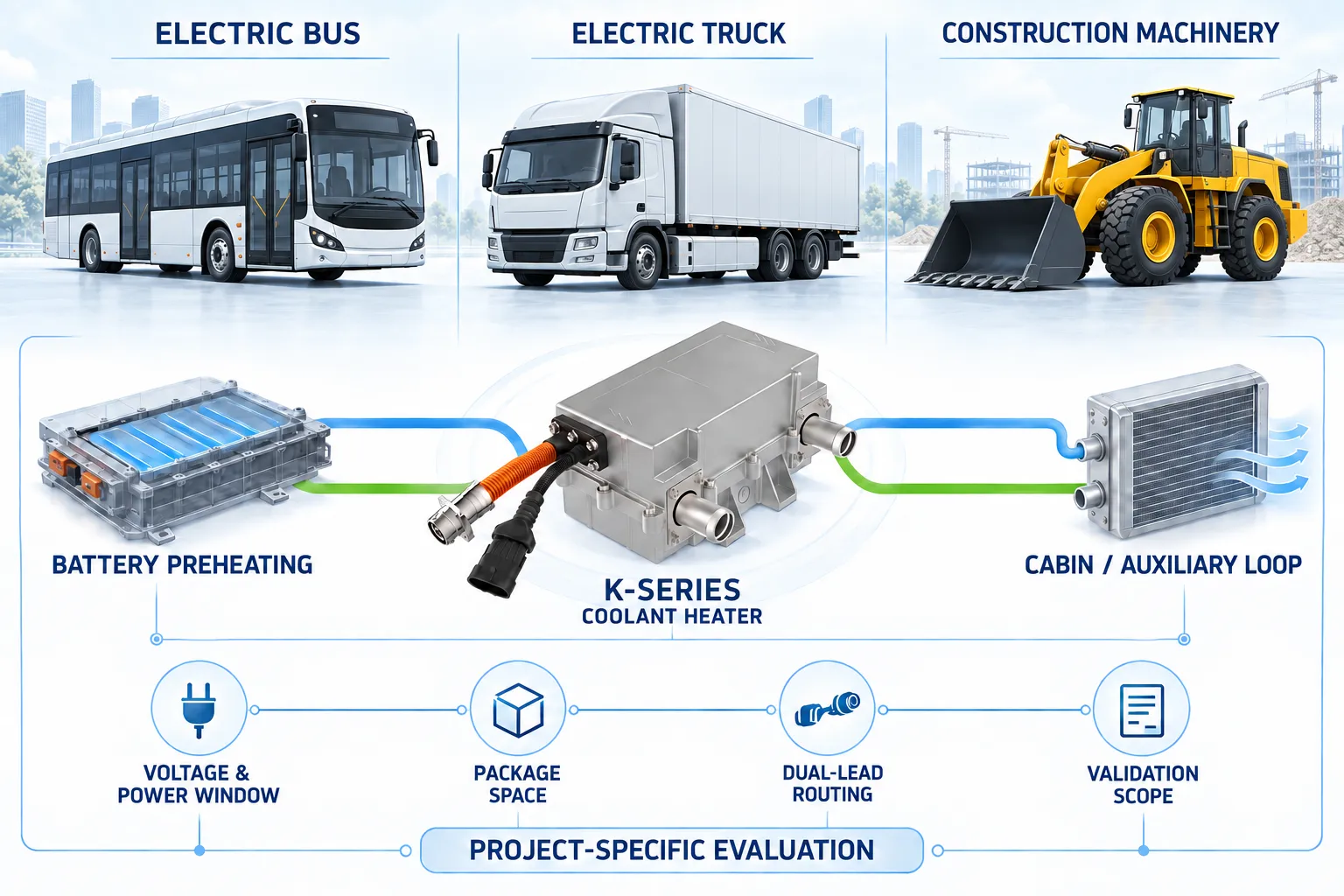
Evaluate the K Series for Bus, Truck and Construction-Machinery Thermal Circuits

The supplied title artwork names electric buses and trucks. Construction machinery is included here as an engineering evaluation path—not as a confirmed application. Final suitability depends on thermal duty, voltage, packaging, environment, interfaces and project validation.

PRODUCT VIEWS

Inspect the Housing, Ports and Dual Cable Exit

Use these views for early review and the released drawing for production packaging.

High Voltage Coolant Heater
QUALIFICATION PACKAGE

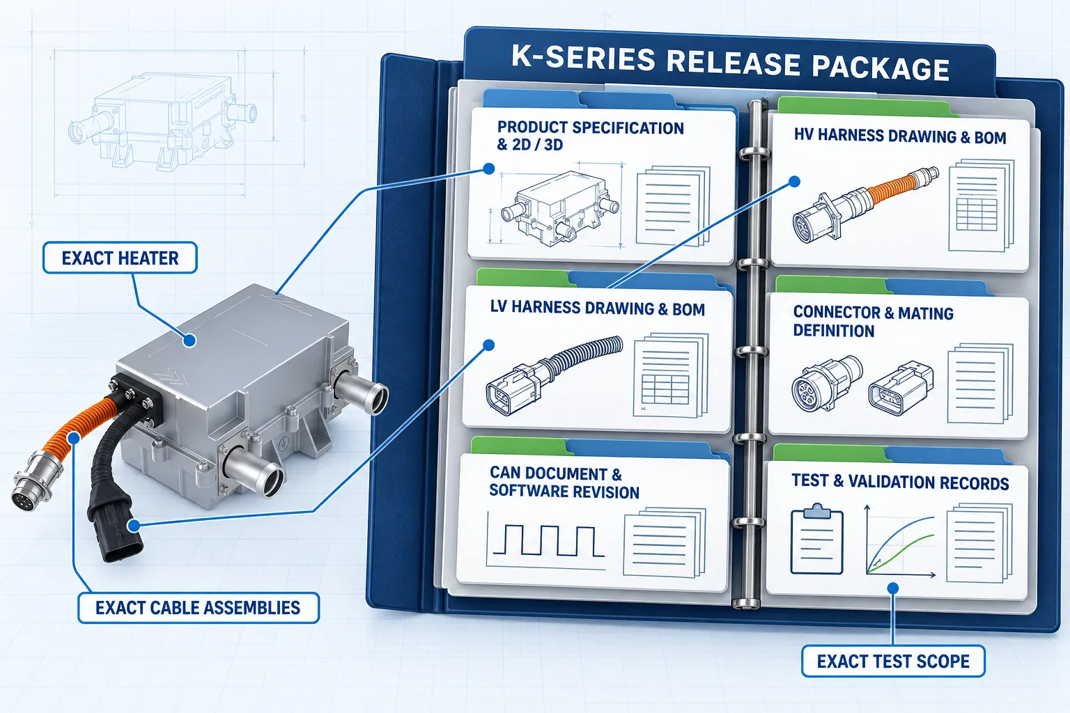
Request Records for the Exact K-Series Release

The source artwork references company certifications and patents. A vehicle program should qualify the exact heater, both cable assemblies, connectors, software and test scope using controlled records.

FAQ

K-Series Dual Flying-Lead Questions

Answers separate supplied facts from details that require a controlled project release.

The supplied imagery shows separate high-voltage and low-voltage flying leads exiting the heater housing. Cable length, connector termination, pinout, sealing, strain relief and vehicle-side responsibility must be defined for the released configuration.
The K-series range is 2–12 kW at 200–800 V DC. Confirm the selected configuration and rating conditions.
The supplied technical panel lists a 200–800 V operating range and describes rated voltage as customizable. Confirm the nominal voltage, minimum and maximum DC voltage and transient requirements for the exact project.
The supplied product-display artwork lists 225 × 170 × 105 mm and Ø25 mm coolant ports. Treat these as an early packaging reference and use the released drawing for tolerances, mounting and hose engagement.
Confirm cable length and exit direction, conductor size and insulation class, connector and mating part numbers, keying, HVIL, shielding or grounding requirements, bend radius and service access.
Confirm conductor count and gauge, CAN and enable assignments, power and ground, termination, labels, sealing, strain relief, diagnostics and harness ownership.
The supplied panel lists CAN bus with enable control, PID control, fault self-diagnosis, automatic power limiting, and overvoltage, undervoltage, overcurrent, short-circuit and overtemperature protection.
The supplied title artwork names electric buses and trucks. Construction machinery is included as an engineering evaluation path and must be confirmed against the duty cycle, voltage, coolant circuit, packaging, vibration, contamination and validation requirements.
Send the voltage window, heat duty, coolant and flow data, temperature and pressure limits, installation envelope, both harness definitions, CAN requirements, validation scope, sample timing and forecast volume.

PROJECT BRIEF

Send One Complete Input Set for the K-Series Review

The fastest useful response comes from combining thermal duty, both harness definitions and packaging constraints.

01

Electrical

Nominal/min/max voltage, current limit, grounding, insulation and HV interface.

02

Control

CAN protocol, enable logic, feedback, diagnostics, fault response and software revision.

03

Thermal

Heat duty, coolant, flow, temperatures, pressure limits and heat-up target.

04

Program

Vehicle, package, sample timing, validation scope, SOP and forecast volume.