Book Appointment Now


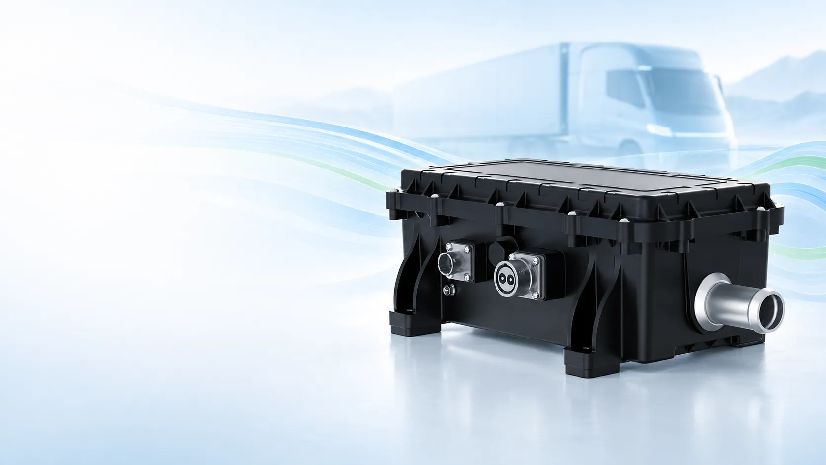
H Series 5–14 kW High Voltage Coolant Heater
A compact 5 kg PTC liquid heater for commercial-EV battery, cabin and auxiliary coolant circuits operating across a published 400–1000 V window.
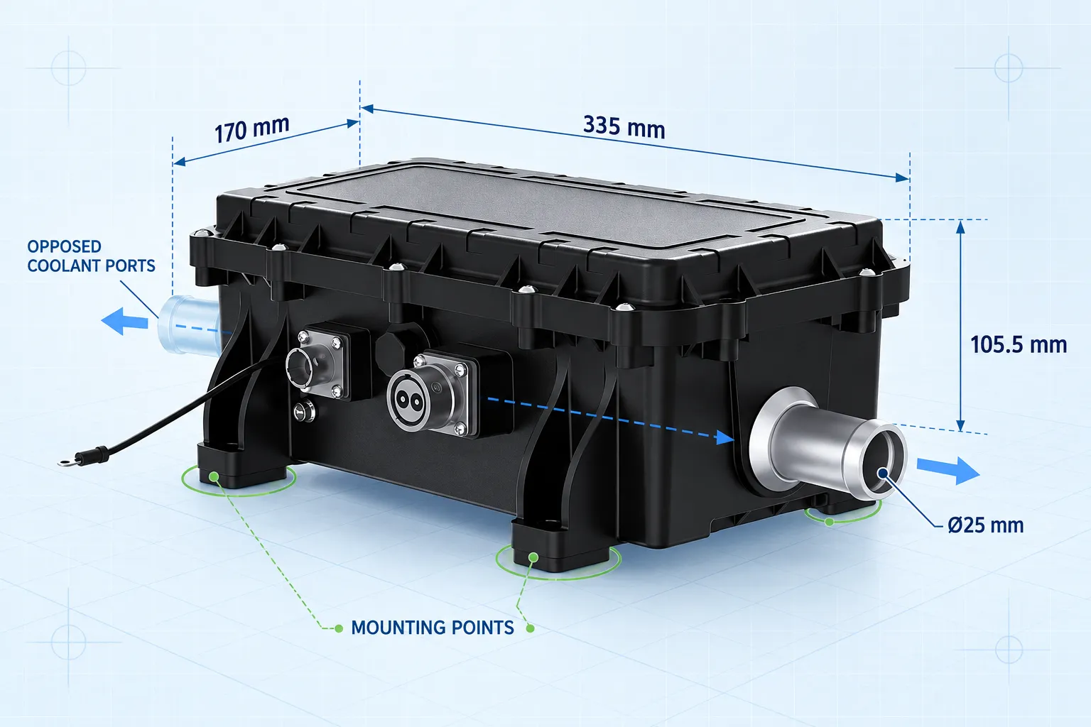
- 335 × 170 × 105.5 mm published envelope
- Ø25 mm coolant ports
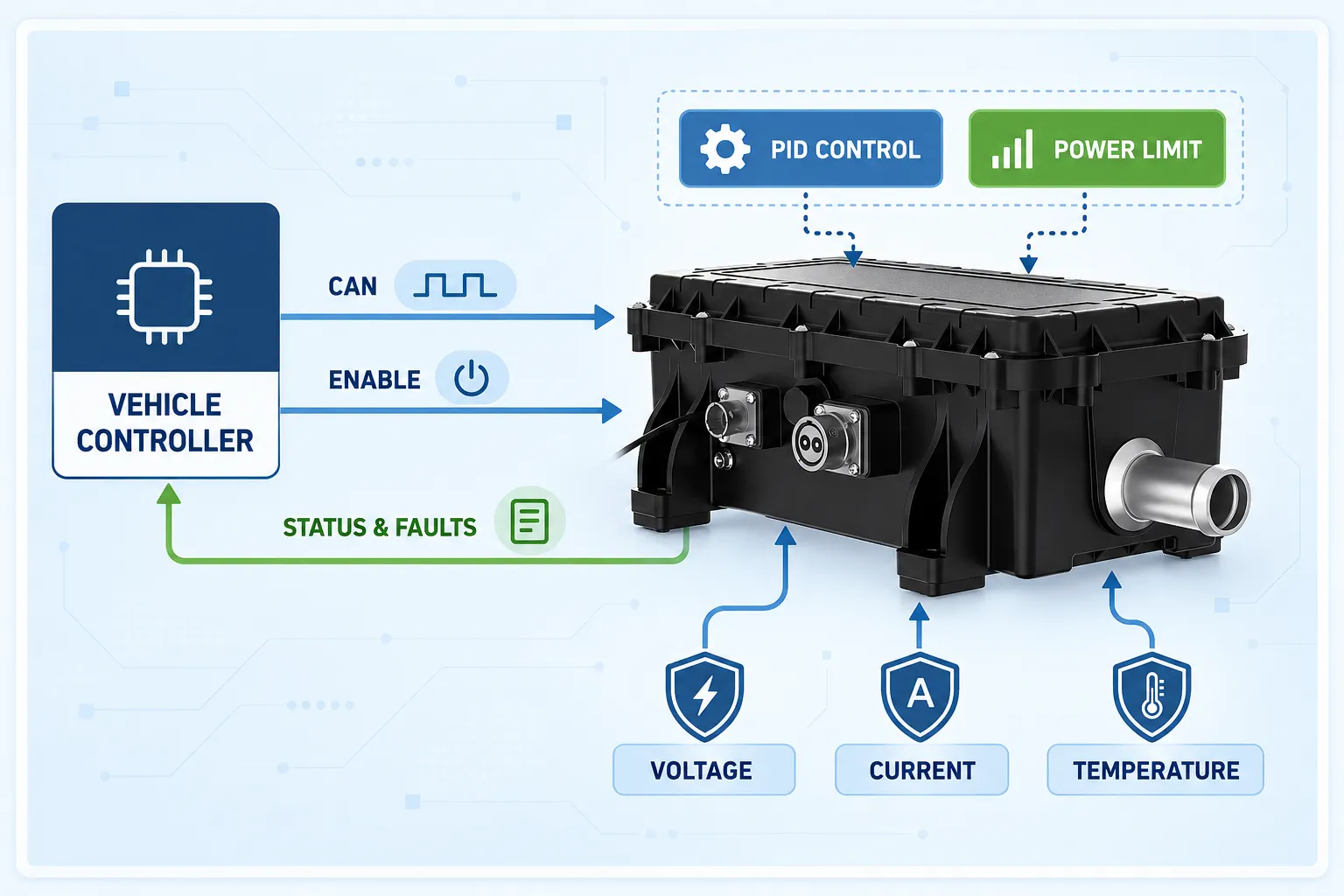
- CAN communication with enable signal
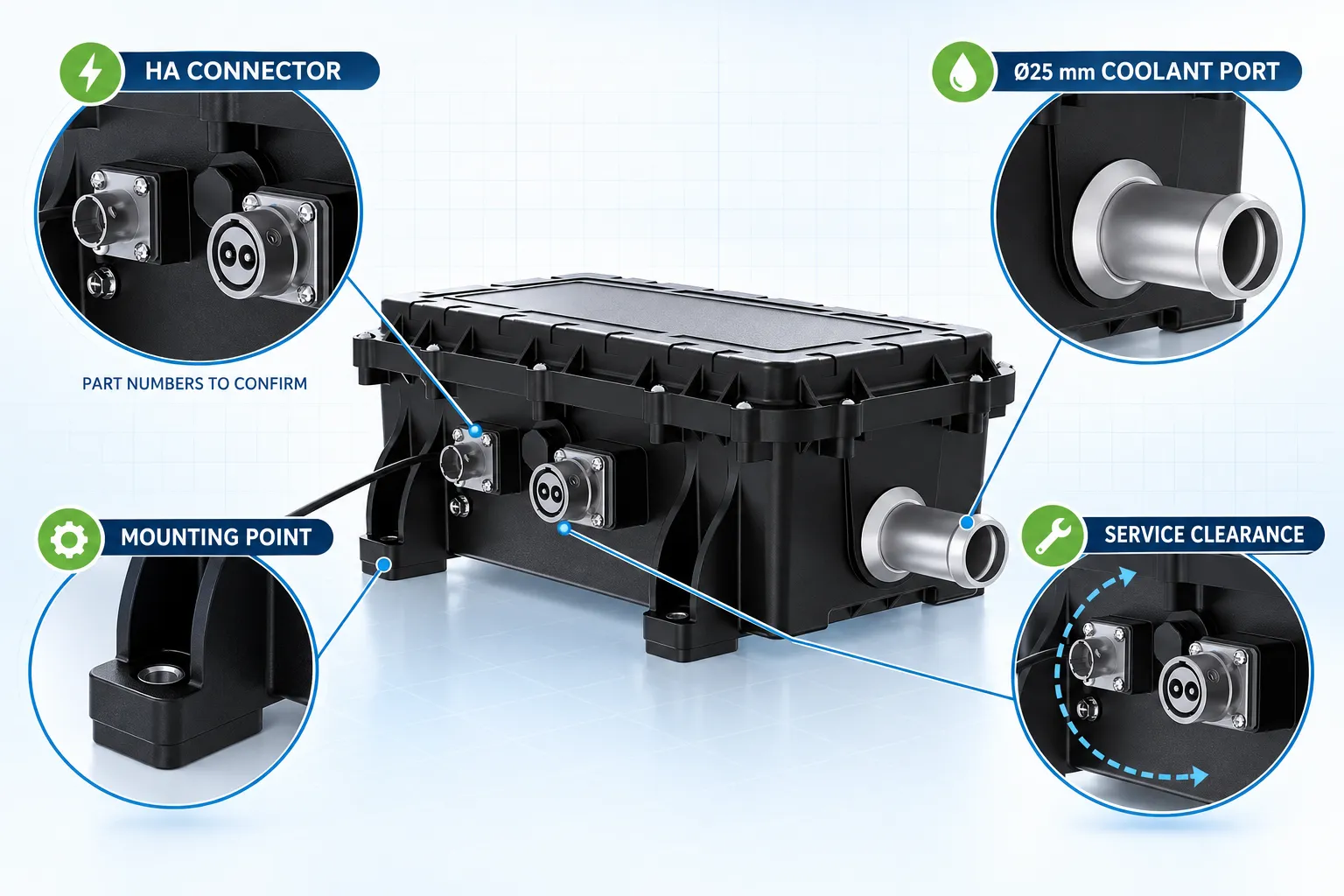
- HA / AVIC-Xinghua connector configuration to confirm
Published rated power
Published operating range
Published product weight
Published ingress protection
Mid-Power Heating in a Compact 5 kg Package
The EVLINK H Series is positioned as a compact high voltage coolant heater for electric-commercial-vehicle thermal circuits. The supplied material lists 5–14 kW rated power, 400–1000 V operation, a 335 × 170 × 105.5 mm envelope and Ø25 mm coolant connections. Its 5 kg published weight supports early packaging studies where a larger 20–24 kW heater may be unnecessary. Final selection must still be based on heat load, coolant conditions, electrical limits, connector release and vehicle validation.
Four Decisions Before You Select the H Series
Use this page to qualify the heater against the vehicle system—not as a substitute for the released drawing or project datasheet.
Heating Duty
Confirm the 5–14 kW range against heat-load calculations, coolant flow and the target heat-up time.
Voltage Window
Verify nominal, minimum, maximum and transient DC voltage within the released configuration.
Package & Coolant
Check the 335 × 170 × 105.5 mm envelope, Ø25 mm ports, hose direction and service space.
HA Interface
Freeze connector part numbers, mating components, HVIL, pin assignment and cable routing.
Check the Envelope, Ports and Mounting Together
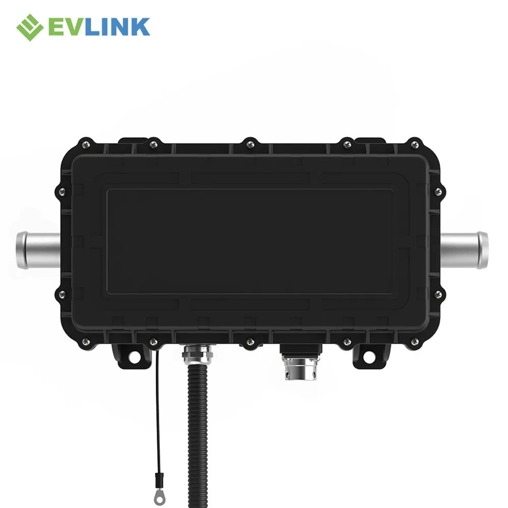
The supplied product-display artwork gives a 335 × 170 × 105.5 mm overall size and Ø25 mm coolant ports. Treat these as an early engineering baseline. The controlled drawing should define mounting-hole locations, tolerances, fasteners, connector clearance, hose engagement, installation orientation and vibration requirements.
- 335 mm length × 170 mm width × 105.5 mm height
- Ø25 mm coolant-port reference
- Opposed coolant-port layout shown
- Connector and cable service clearance required
H Series Engineering Baseline
The values below are transcribed from the supplied technical and dimension artwork. The released specification governs the final order.
5–14 kW in the supplied technical specification; confirm released project rating
Customizable — confirm nominal voltage and exact configuration
400–1000 V
335 × 170 × 105.5 mm in the supplied dimension artwork
Ø25 mm shown in the supplied product display
5 kg
−40 °C to +85 °C
≥100 MΩ at DC1000 V, high-voltage section
IP67
CAN communication with enable signal
PID control, fault self-diagnosis and automatic power limiting
Overvoltage, undervoltage, overcurrent, short-circuit and overheat protection
ISO 11452 Class 3 is stated in the supplied material; request the applicable report and test scope
2 years is listed; confirm applicable commercial terms
Define Vehicle Behavior Before Software Release
CAN communication, an enable signal, PID control, fault self-diagnosis and automatic power limiting are listed in the supplied material. Convert those labels into a project-specific control agreement covering state transitions, feedback, diagnostics, derating and shutdown behavior.
- CAN command, status and fault signals
- Enable, wake, shutdown and restart logic
- Voltage, current and temperature thresholds
- Derating and automatic power-limiting behavior
- Software revision and change control
Freeze the HA Connector and Coolant Interfaces
The source folder identifies an HA configuration associated with AVIC and a Xinghua high-voltage interface. That folder label is useful for internal routing but is not enough for production release. Publish exact connector claims only after the controlled part numbers and mating definitions are confirmed.
Electrical
Connector part numbers, keys, HVIL, pins, voltage/current rating and mating parts.
Coolant
Port tolerance, hose specification, flow direction, pressure and pressure-drop limits.
Mechanical
Mounting holes, fasteners, orientation, vibration load and cable bend radius.
Service
Disconnect access, drainage, diagnostics and replacement clearance.
Where the H Series May Be Evaluated
Vehicle labels are only a starting point. Thermal duty, voltage, environment and interfaces determine fit.
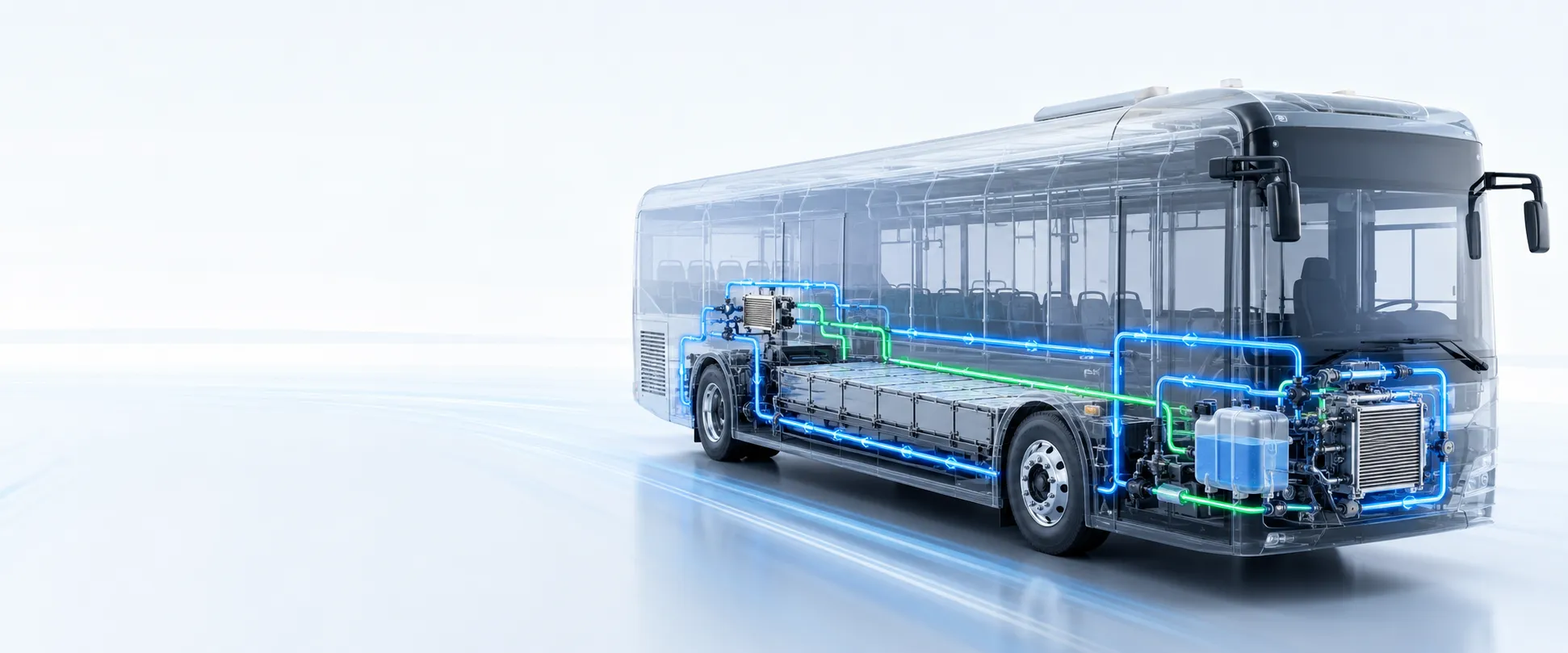
Electric Buses
Evaluate for battery, cabin or auxiliary liquid-heating circuits when the 5–14 kW duty and vehicle voltage window align.
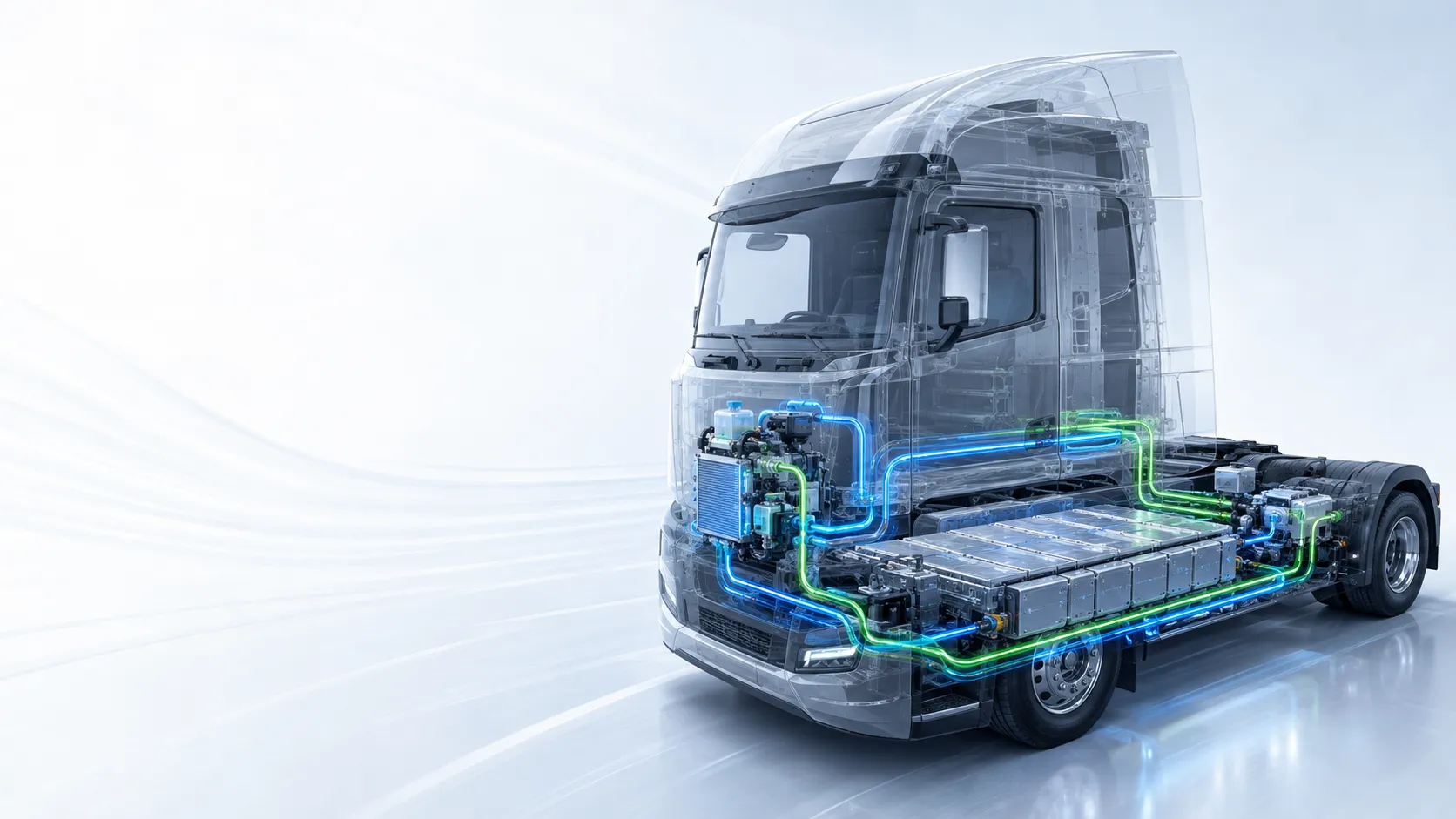
Electric Trucks
Use as a candidate for medium-duty thermal circuits after verifying heat load, coolant conditions, installation space and controls.
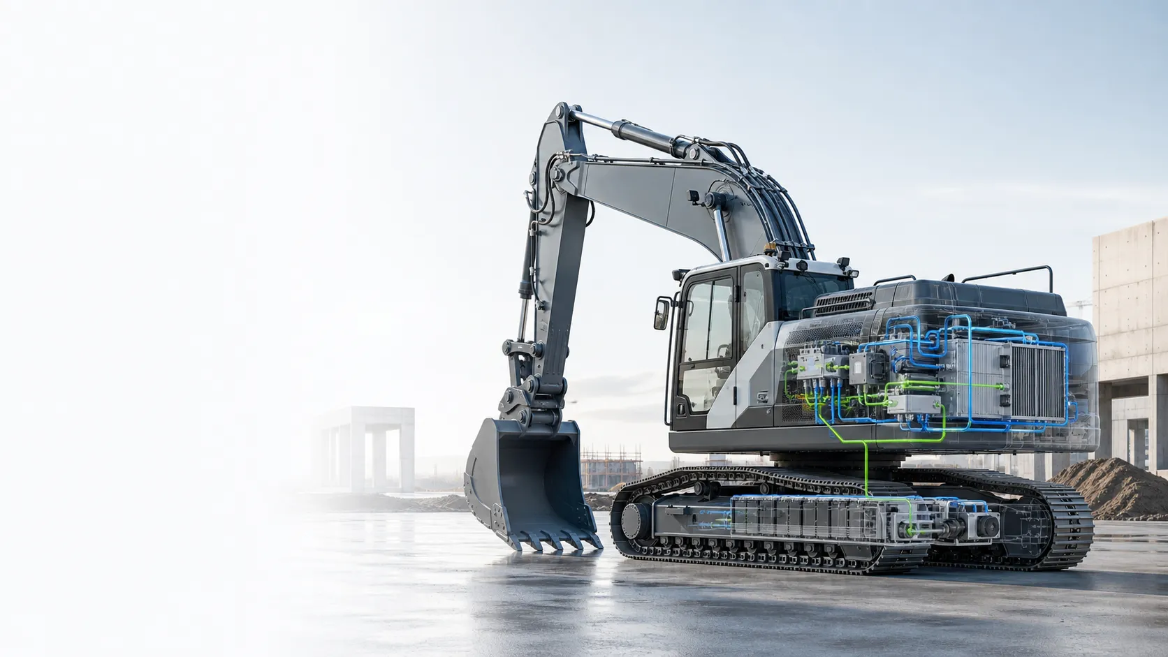
Construction Machinery
Evaluate for off-highway high-voltage coolant systems after reviewing vibration, contamination, ambient and duty cycle.
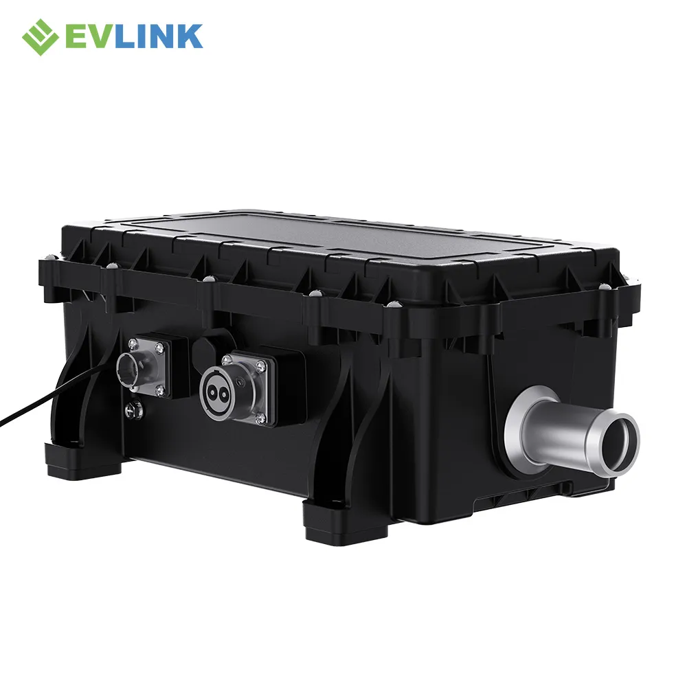
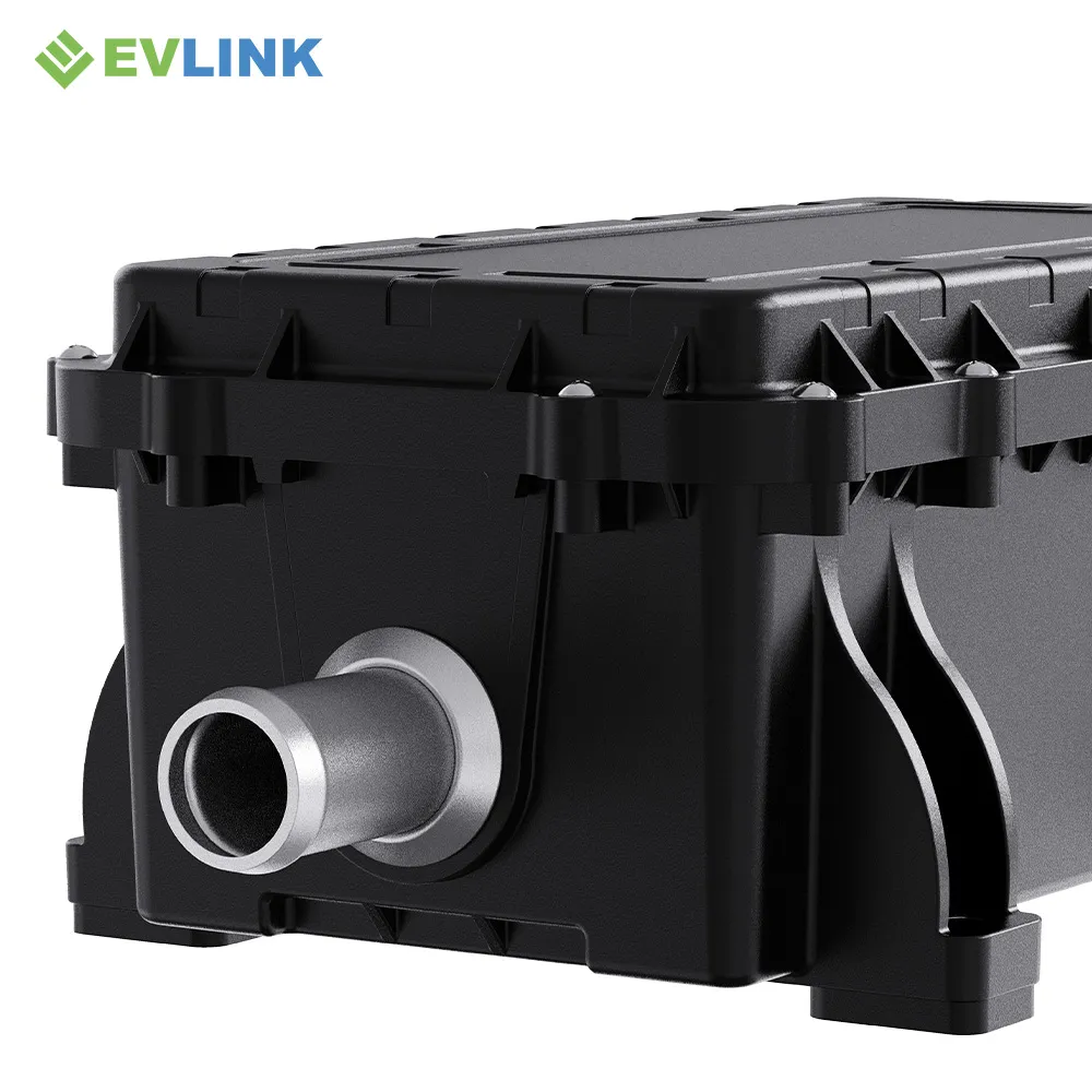
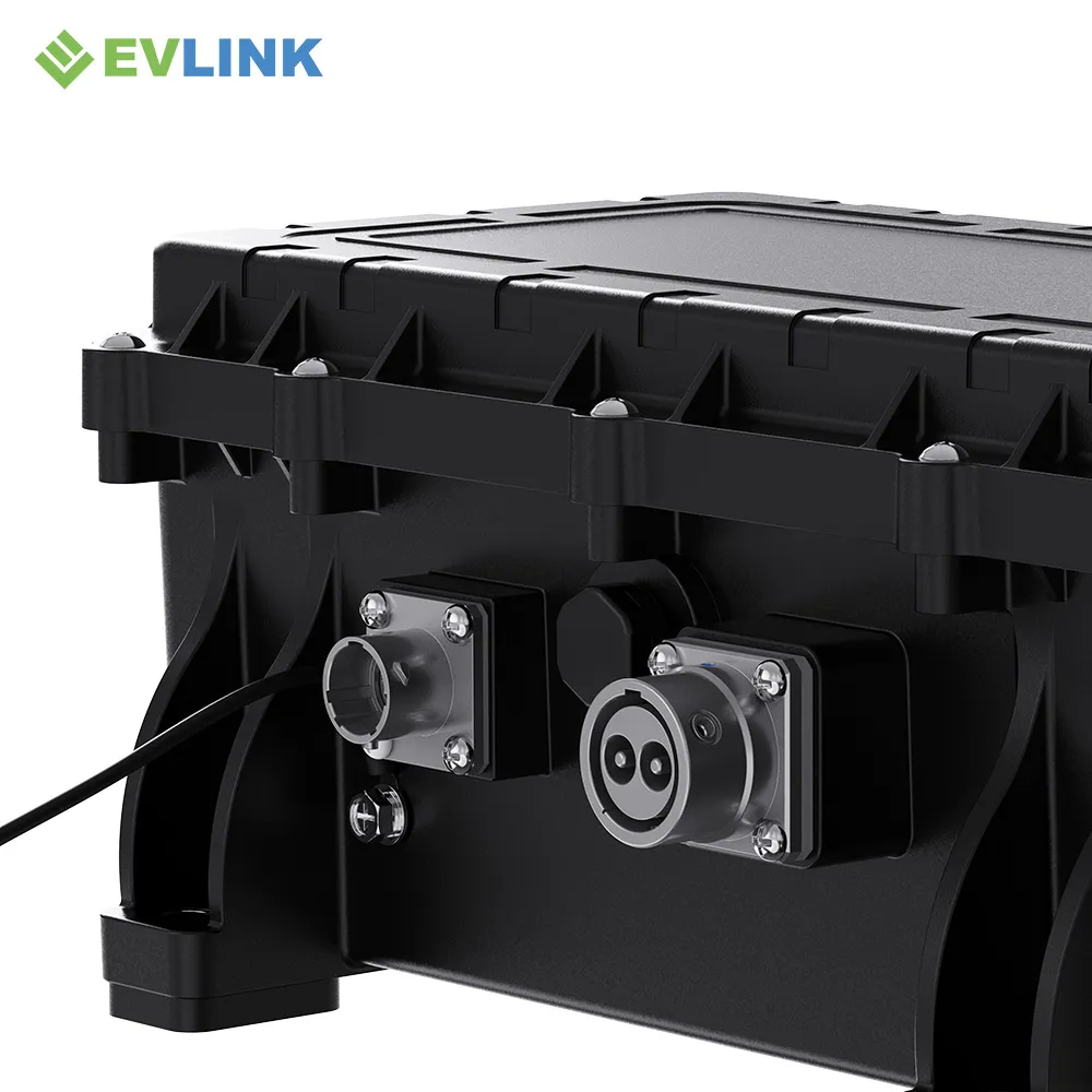
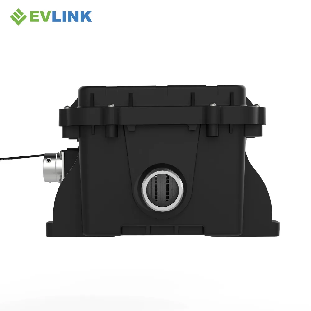
Review the Housing and Interfaces from Multiple Angles
Use these images for early visual review and the released 2D or 3D drawing for packaging approval.
Request Documents for the Exact H-Series Configuration
The supplied artwork references certifications and performance classes. Project qualification should rely on controlled records that match the exact hardware, software and connector release—not on a family-level marketing panel alone.
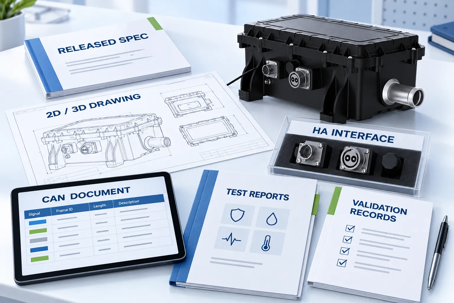
- Released product specification and 2D / 3D drawing
- HA connector and mating-component definition
- CAN document and software revision
- Applicable EMC, ingress, electrical-safety and environmental reports
- Prototype inspection and project validation records
- Approved warranty and commercial terms
H Series Engineering Questions
Answers are based on the supplied artwork and deliberately point back to controlled project documents.
Send the Inputs That Determine Heater Fit
A useful recommendation starts with system conditions, not only a requested kilowatt value.
Electrical
Nominal/min/max voltage, transient limits, connector family, HVIL and grounding.
Thermal
Heat load, heat-up time, inlet/outlet temperatures, coolant, flow and pressure.
Vehicle
Vehicle type, installation envelope, ambient, vibration, duty cycle and service access.
Program
CAN requirements, validation scope, SOP timing, sample quantity and forecast volume.