H SERIES · LV FLYING-LEAD CONFIGURATION

H2 Series 5–14 kW High Voltage Coolant Heater with Low-Voltage Flying Lead

An interface-focused PTC liquid-heater configuration for commercial EV projects that require a fixed low-voltage harness exit alongside a detachable high-voltage connection.

High Voltage Coolant Heater
5–14 kW

Technical-panel rated power

400–1000 V

Published operating range

LV Pigtail

Low-voltage harness path

IP67

Published ingress protection

CONFIGURATION FIRST

Why the Low-Voltage Flying Lead Changes the Release Work

The heating specification is only one side of this configuration. The vehicle harness boundary must be agreed before drawings, samples and software are frozen.

01

Fixed Cable Exit

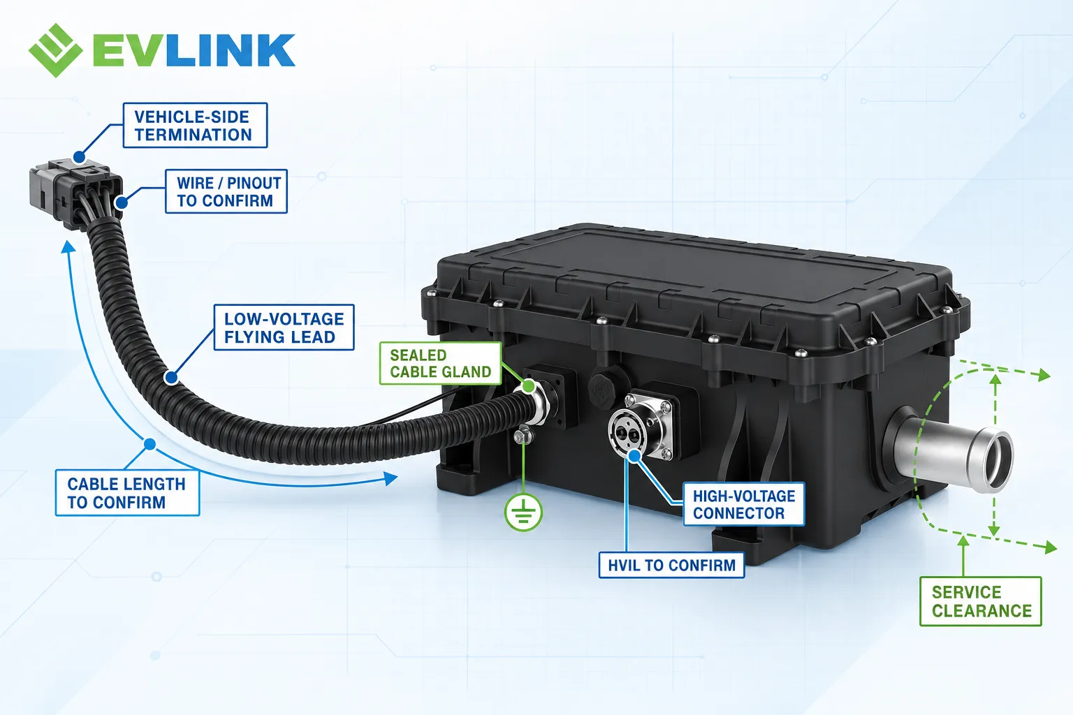
The low-voltage cable leaves the housing through a sealed gland, so length, routing and bend radius become part of the package release.

02

Vehicle-Side Termination

The project must define whether the pigtail is supplied bare, terminated or mated to a vehicle-specific connector.

03

Control Ownership

CAN, enable, status and fault wires require an agreed pinout, signal matrix and responsibility boundary.

High Voltage Coolant Heater
HARNESS RELEASE

Freeze the Cable and Connector Boundary

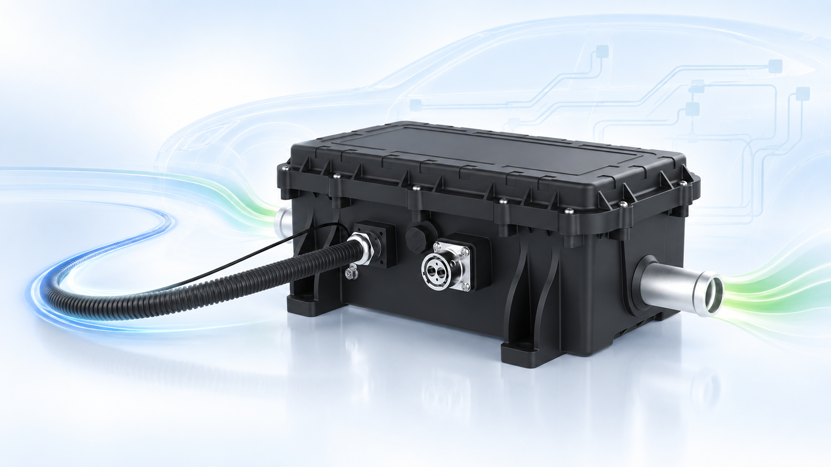
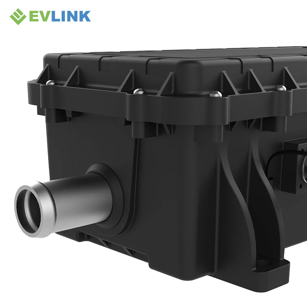
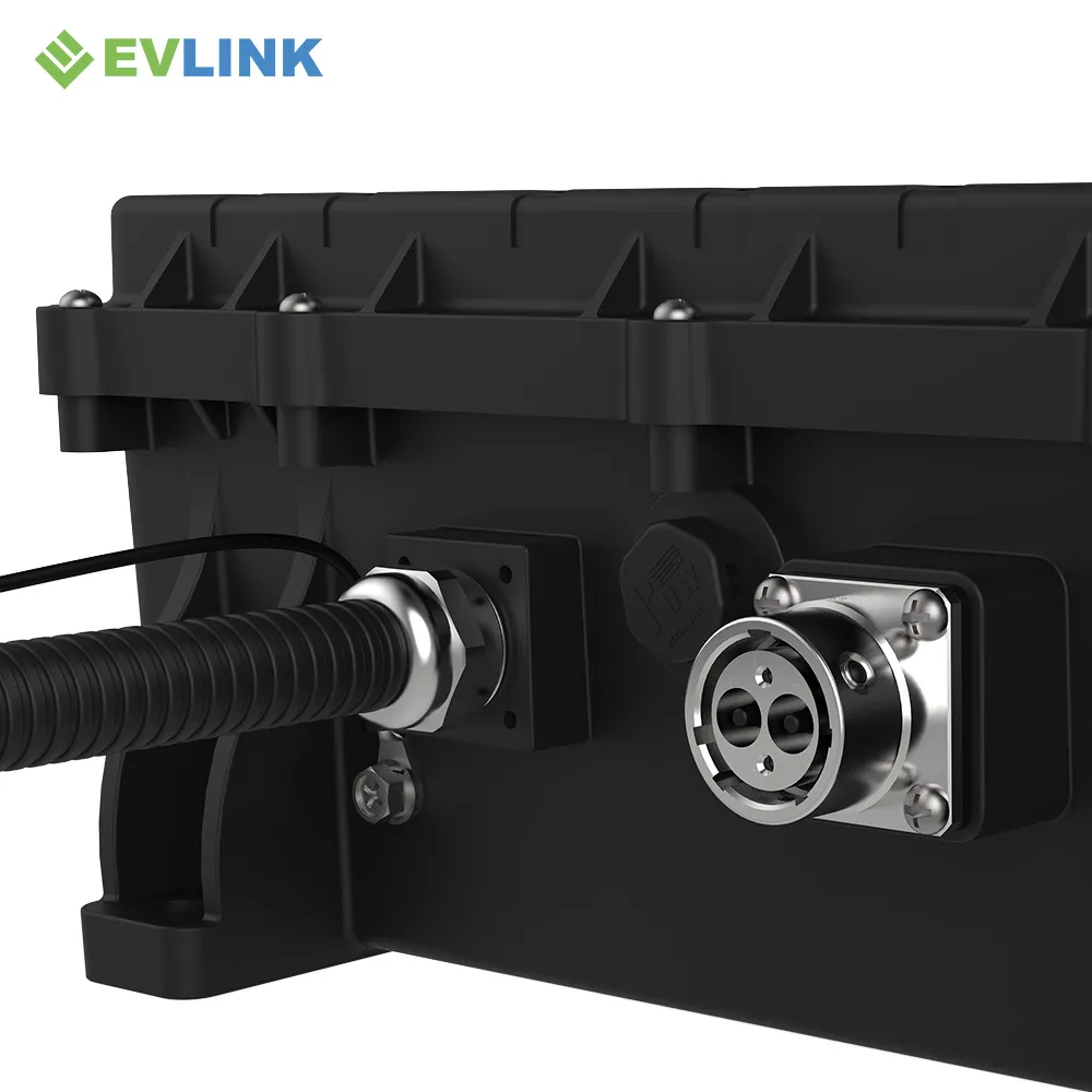
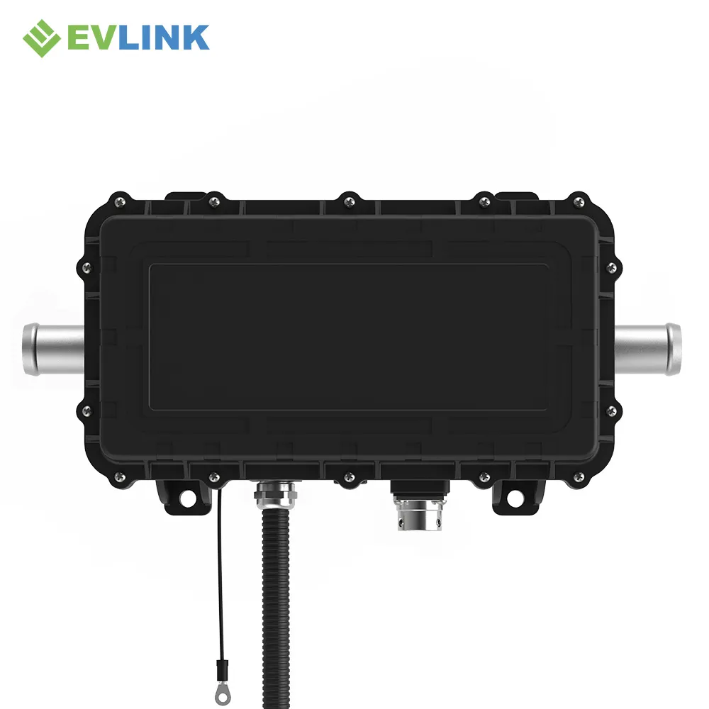
The source images show a corrugated low-voltage lead exiting through a gland and a separate circular high-voltage connector. The exact parts and assignments are not published in the supplied artwork, so the project release must define them explicitly.

SELECTION GATE

When This Configuration Is the Better Starting Point

Choose around the vehicle harness architecture, not around a product photo.

USE

Fixed LV Harness Path

Start here when the project prefers a sealed low-voltage pigtail and can control its vehicle-side termination.

REVIEW

Detachable LV Interface

Review the alternate H-Series configuration when the vehicle requires a detachable low-voltage socket at the heater.

Do not release by connector appearance alone

Confirm controlled part numbers, keys, mating components, cable construction, pinout and supplier responsibility before quotation or prototype build.

MECHANICAL BASELINE

Package the Heater and Pigtail as One Assembly

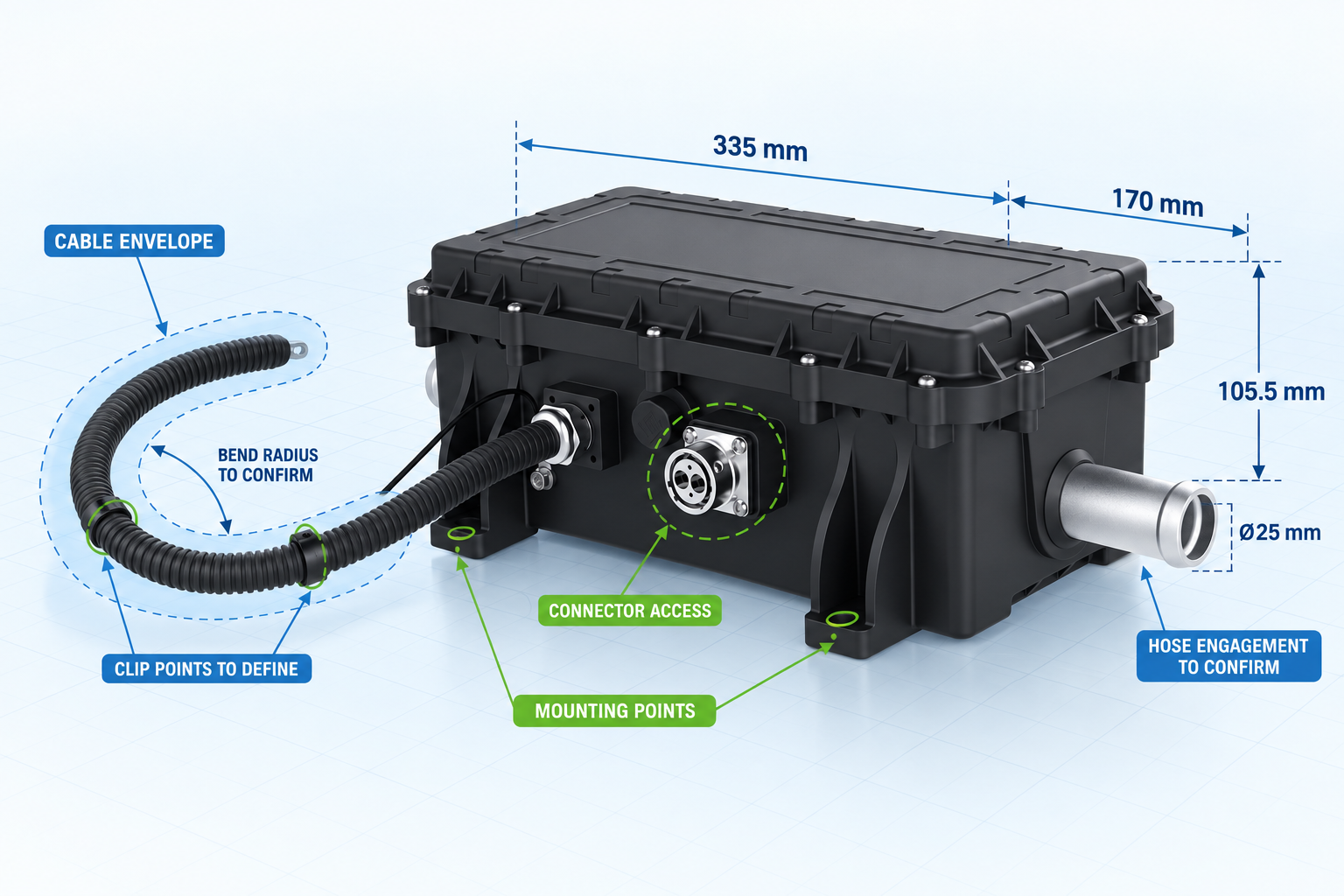
The supplied product display lists 335 × 170 × 105.5 mm and Ø25 mm coolant ports. The fixed low-voltage lead adds a cable envelope that must be included in the vehicle package review.

High Voltage Coolant Heater
TECHNICAL SPECIFICATIONS

Published H-Series LV-Lead Baseline

Values are transcribed from the supplied technical and product-display artwork. Resolve the power-range conflict before publication.

Rated Power

5–14 kW series range; confirm the ordered configuration and rating conditions

Rated Voltage

Customizable — confirm the released project configuration

Operating Voltage Range

400–1000 V

Product Size

335 × 170 × 105.5 mm in the supplied product display

Coolant Port

Ø25 mm shown in the supplied product display

Weight

5 kg

Insulation Resistance

≥100 MΩ at DC1000 V, high-voltage section

Dielectric Strength

≥1200 V, ceramic heating element

Peak Current

≤1.5 × rated current

Ingress Protection

IP67

Operating / Storage Temperature

−40 °C to +85 °C

Communication

CAN bus with enable control

Control

PID control, fault self-diagnosis and automatic power limiting

Protection

Overvoltage, undervoltage, overcurrent, short circuit and overtemperature

EMC

Class 3 is listed; request the applicable standard and report scope

Warranty

2 years is listed; confirm configuration and regional applicability

INTEGRATION WORKFLOW

Move from Harness Definition to Vehicle Validation

The flying lead makes interface ownership visible. Freeze each layer in sequence.

01

Define

Set voltage window, cable construction, connector parts, pinout, CAN signals and fault behavior.

02

Package

Check routing, bend radius, sealing, mounting, coolant connections and service access.

03

Prototype

Inspect the cable assembly, mating fit, polarity, communication and coolant circuit before vehicle test.

04

Validate

Run the agreed electrical, thermal, EMC, ingress, vibration and durability scope.

High Voltage Coolant Heater
CONTROL & PROTECTION

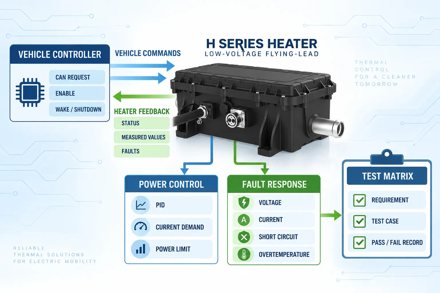
Turn Feature Names into Testable Requirements

A

Vehicle Commands

CAN requests, enable logic, wake-up, shutdown and restart behavior.

B

Heater Feedback

Status, measured values, derating, faults and diagnostic persistence.

C

Power Control

PID ownership, current demand, automatic power limiting and thermal limits.

D

Fault Response

Voltage, current, short-circuit and overtemperature thresholds and recovery.

APPLICATION FIT

Where a Fixed Low-Voltage Lead May Be Practical

Suitability depends on the vehicle architecture and environment, not the vehicle label alone.

01

Electric Trucks

Evaluate when the vehicle harness can accept a fixed LV lead and the released thermal duty matches the coolant circuit.

02

Electric Buses

Use as a candidate for battery, cabin or auxiliary liquid heating after checking duty, voltage, packaging and serviceability.

03

Construction Machinery

Evaluate after defining cable protection, vibration, contamination, temperature exposure and duty cycle.

PRODUCT VIEWS

Inspect the Cable Exit, Connector and Coolant Interfaces

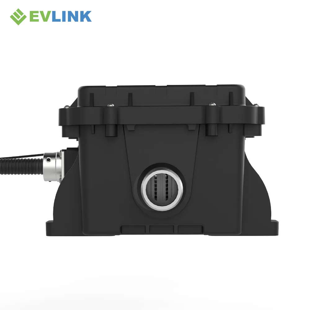
These images support early visual review; use the released drawing for production packaging.

High Voltage Coolant Heater
RELEASE EVIDENCE

Ask for Configuration-Specific Records

The source artwork lists certifications and performance classes, but a vehicle program needs records tied to the exact H-Series hardware, flying-lead assembly, connector, software and test scope.

High Voltage Coolant Heater
FAQ

H-Series Low-Voltage Flying-Lead Questions

The answers separate supplied facts from items that require a controlled project release.

This configuration is identified by the supplied folder as using an HA/AVIC high-voltage interface with a low-voltage flying lead. Confirm cable length, wire specification, termination, pinout and strain relief for the released project version.
The supplied technical panel lists 5–14 kW, while the supplied title artwork says 5–14 kW. This template temporarily follows the technical panel. Resolve the conflict before publishing, quoting or adding Product schema.
The supplied technical panel lists 400–1000 V and describes rated voltage as customizable. Confirm nominal voltage, minimum and maximum DC voltage and transient requirements for the exact release.
The supplied product-display artwork lists 335 × 170 × 105.5 mm and Ø25 mm coolant ports. Use the released drawing for tolerances, mounting points, hose engagement and service clearances.
Confirm cable exit and length, conductor count and gauge, insulation and temperature class, sealing, strain relief, terminal or mating connector, labels, CAN and enable assignments, and vehicle-harness responsibility.
The source lists CAN bus with enable control, PID control, fault self-diagnosis, automatic power limiting, plus overvoltage, undervoltage, overcurrent, short-circuit and overtemperature protection.
Send the voltage window, heat duty, coolant and flow, temperature targets, pressure limits, installation envelope, high-voltage connector, low-voltage harness definition, CAN requirements, validation scope, timing and volume.

PROJECT BRIEF

Send the Harness Details with the Thermal Requirements

A qualified recommendation needs both the coolant-heater duty and the vehicle interface boundary.

01

Electrical

Nominal/min/max voltage, current limit, grounding, insulation and HV connector.

02

LV Harness

Cable length, wires, gauge, pinout, termination, CAN, enable and strain relief.

03

Thermal

Heat duty, target heat-up time, coolant, flow, temperatures and pressure limits.

04

Program

Vehicle type, package, validation scope, sample timing, SOP and forecast volume.