Book Appointment Now


PRODUCTS | ELECTRIC THERMAL MANAGEMENT
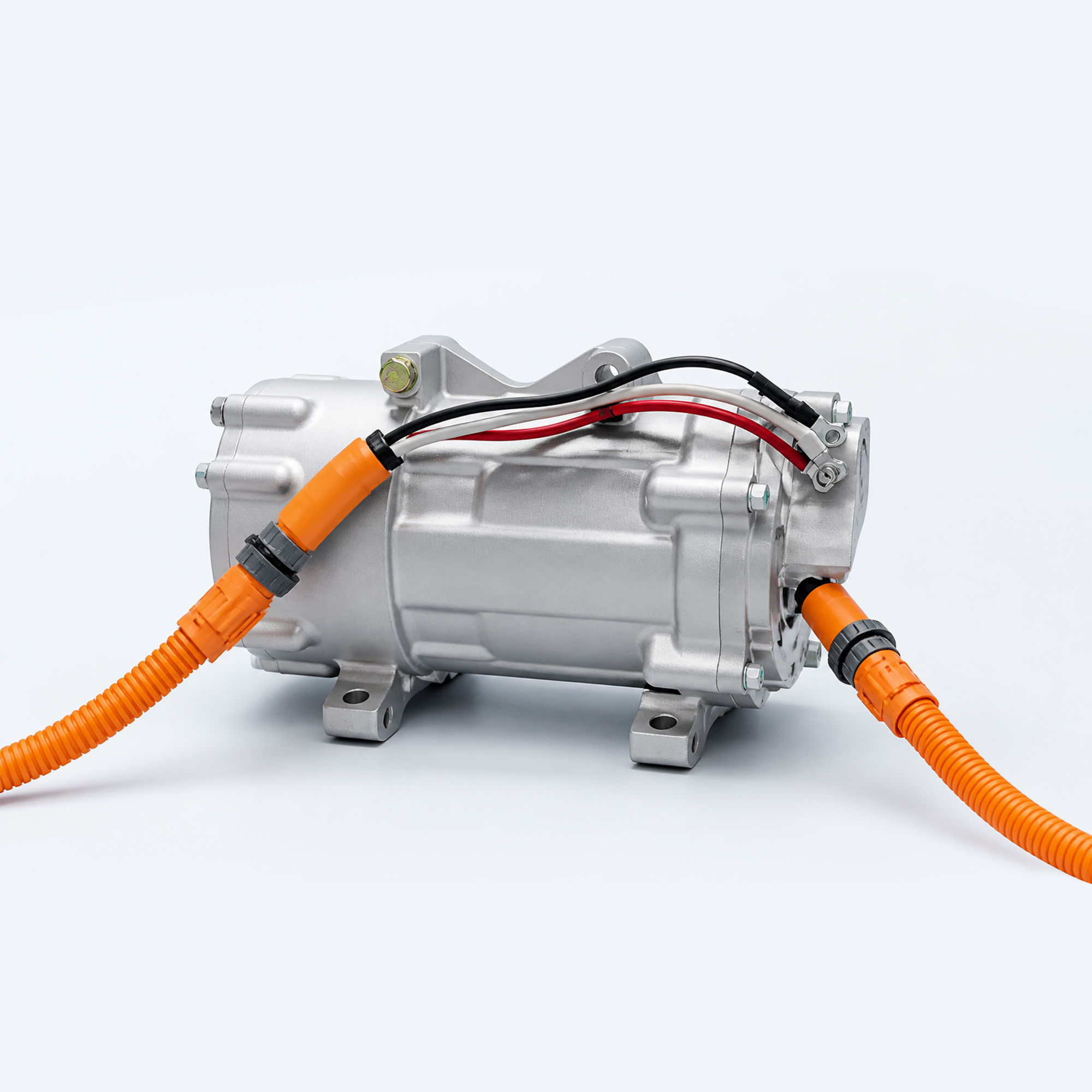
Electric Compressor for EV Thermal Management Systems
Reference compressor options for electric-vehicle HVAC, heat-pump and battery-cooling circuits across commercial and off-highway platforms.
Select by thermal operating point, voltage window, refrigerant, displacement, speed range, control interface, installation envelope and validation requirement—not by voltage or displacement alone.
14–120 cc
Reference displacement
24–960 V
Model-specific options
R134a / R1234yf
Reference refrigerants
SYSTEM ROLE
One Compressor, Three Different Engineering Contexts
The correct compressor is determined by the actual refrigerant-cycle operating points and vehicle control architecture.
01
Cabin HVAC
Provide refrigerant compression for passenger-compartment cooling on electric commercial and off-highway vehicles.
02
Heat-Pump System
Support heating-cycle integration only when the selected compressor has a released heat-pump operating envelope.
03
Battery Cooling
Drive the refrigerant circuit serving a chiller or battery-cooling loop under defined charging and duty-cycle conditions.
PORTFOLIO OVERVIEW
Reference Selection Range
The supplied handbook contains 18 model references. Use this range to structure buyer selection, then replace or approve each entry against EVLINK’s released supply portfolio.
Reference Displacement Range
14–120 cc across the supplied model portfolio
Reference Rated Voltage Options
24–960 V depending on the specific model
Reference Speed Range
1,000–9,000 rpm depending on the specific model
Refrigerant
R134a / R1234yf
Lubricating Oil
POE
Storage Temperature
−40°C to +125°C
Operating Temperature
−40°C to +85°C; source marks this as non-heat-pump condition
Cooling Method
Suction-gas cooling
Protection
Source states IP67 / IPX6K9K; exact rating and test condition require model confirmation
REFERENCE MODEL MATRIX
Compare Displacement, Speed, Voltage and Mass
This model matrix answers high-intent engineering questions while keeping unverified performance claims out of the page.
Reference 01
14 cc
Speed Range: 1,000–6,000 rpm
Rated Voltage Options: 24 / 48 / 80 / 90 / 144 / 360 V
Oil-Free Mass: ≤5 kg
Reference Leakage: ≤5 g/year
Reference 02
14 cc
Speed Range: 1,000–6,000 rpm
Rated Voltage Options: 24 / 48 / 80 / 90 / 144 / 360 V
Oil-Free Mass: ≤5 kg
Reference Leakage: ≤5 g/year
Reference 03
20 cc
Speed Range: 1,000–6,000 rpm
Rated Voltage Options: 80 / 96 / 144 / 360 / 600 / 800 V
Oil-Free Mass: ≤6 kg
Reference Leakage: ≤6 g/year
Reference 04
20 cc
Speed Range: 1,000–6,000 rpm
Rated Voltage Options: 24 / 48 / 80 / 90 / 144 / 360 V
Oil-Free Mass: ≤6 kg
Reference Leakage: ≤6 g/year
Reference 05
22 cc
Speed Range: 1,000–6,000 rpm
Rated Voltage Options: 24 / 48 / 80 / 90 / 144 / 360 V
Oil-Free Mass: ≤6 kg
Reference Leakage: ≤6 g/year
Reference 06
27 cc
Speed Range: 1,000–6,000 rpm
Rated Voltage Options: 80 / 96 / 144 / 360 / 600 / 800 V
Oil-Free Mass: ≤6 kg
Reference Leakage: ≤6 g/year
Reference 07
27 cc
Speed Range: 1,000–6,000 rpm
Rated Voltage Options: 24 / 48 / 80 / 90 / 144 / 360 V
Oil-Free Mass: ≤6 kg
Reference Leakage: ≤6 g/year
Reference 08
27 cc
Speed Range: 1,000–6,000 rpm
Rated Voltage Options: 24 / 48 / 80 / 90 / 144 / 360 V
Oil-Free Mass: ≤6 kg
Reference Leakage: ≤6 g/year
Reference 09
34 cc
Speed Range: 1,000–6,000 rpm
Rated Voltage Options: 80 / 96 / 144 / 360 / 600 / 800 V
Oil-Free Mass: ≤6 kg
Reference Leakage: ≤10 g/year
Reference 10
34 cc
Speed Range: 1,000–6,000 rpm
Rated Voltage Options: 24 / 48 / 80 / 90 / 144 / 360 V
Oil-Free Mass: ≤6 kg
Reference Leakage: ≤10 g/year
Reference 11
34 cc
Speed Range: 1,000–6,000 rpm
Rated Voltage Options: 24 / 48 / 80 / 90 / 144 / 360 V
Oil-Free Mass: ≤6 kg
Reference Leakage: ≤10 g/year
Reference 12
34 cc
Speed Range: 1,000–9,000 rpm
Rated Voltage Options: 80 / 96 / 144 / 360 / 600 / 800 V
Oil-Free Mass: ≤7.5 kg
Reference Leakage: ≤10 g/year
Reference 13
40 cc
Speed Range: 1,000–8,500 rpm
Rated Voltage Options: 80 / 96 / 144 / 360 / 600 / 800 V
Oil-Free Mass: ≤8 kg
Reference Leakage: ≤10 g/year
Reference 14
52 cc
Speed Range: 1,000–8,500 rpm
Rated Voltage Options: 360 / 540 / 600 / 800 / 960 V
Oil-Free Mass: ≤8.5 kg
Reference Leakage: ≤10 g/year
Reference 15
50 cc
Speed Range: 1,000–6,000 rpm
Rated Voltage Options: 360 / 540 / 600 / 800 / 960 V
Oil-Free Mass: ≤10.5 kg
Reference Leakage: ≤12 g/year
Reference 16
66 cc
Speed Range: 2,000–6,000 rpm
Rated Voltage Options: 360 / 540 / 600 / 800 / 960 V
Oil-Free Mass: ≤11 kg
Reference Leakage: ≤12 g/year
Reference 17
80 cc
Speed Range: 2,000–6,000 rpm
Rated Voltage Options: 360 / 540 / 600 / 800 / 960 V
Oil-Free Mass: ≤14 kg
Reference Leakage: ≤14 g/year
Reference 18
120 cc
Speed Range: 2,000–6,000 rpm
Rated Voltage Options: 360 / 540 / 600 / 800 / 960 V
Oil-Free Mass: ≤15 kg
Reference Leakage: ≤14 g/year
SELECTION PRINCIPLE
Cooling Capacity Must Be Matched at the Required Operating Point
Displacement and maximum speed do not by themselves define usable capacity, efficiency, discharge temperature or NVH performance.
The final selection requires the performance map at the target evaporating temperature, condensing temperature, superheat, subcooling, refrigerant and speed. Publish performance curves only after the model and test conditions are released for public use.
Required Inputs
- Cooling or heat-pump capacity target
- Evaporating and condensing conditions
- Refrigerant and oil specification
- DC voltage operating window
- Speed and control strategy
- NVH and validation targets
VEHICLE INTEGRATION
How the Electric Compressor Connects to the Thermal System
Voltage, refrigerant conditions, control ownership and the downstream thermal job must be defined together.
PROJECT INPUTS
Define the Operating Point
- Voltage and DC window
- Cooling-capacity target
- Refrigerant and oil
- Evaporating/condensing conditions
- CAN and control strategy
CORE COMPONENT
Electric Compressor
Refrigerant compression matched to voltage, speed, thermal demand and control boundaries.
→
THERMAL JOBS
Cabin HVAC
Cooling and comfort
Heat Pump
Heating-cycle integration
BTMS Chiller
Battery cooling circuit
INTEGRATION REVIEW
Four Interfaces Must Be Closed Before Model Release
A catalogue voltage match is only the start of compressor selection.
01
Electrical
Nominal/minimum/maximum DC voltage, current limit, pre-charge, interlock, insulation, grounding and HV connector.
02
Refrigerant Circuit
Refrigerant, POE oil, suction/discharge conditions, fittings, charge, cleanliness and liquid-return protection.
03
Control & CAN
Speed command, CAN matrix, wake/sleep, enable, status, faults, power limits, diagnostics and fallback behavior.
04
Mechanical & NVH
Envelope, mounting points, orientation, hose routing, vibration isolation, acoustic target and service clearance.
APPLICATION AREAS
Electric Compressors for Commercial and Off-Highway EV Platforms
Every platform requires a separate operating-point, voltage, packaging and validation review.
Electric Bus
HVAC and battery-cooling integration for route, charging and passenger-comfort duty cycles.
Electric Truck
Thermal-system integration for payload, grade, depot and fast-charging conditions.
Electric Mining Truck
High-load cooling selection for dust, vibration, altitude and sustained haul cycles.
Construction Machinery
Compressor selection for variable work cycles and restricted installation space.
Agricultural Machinery
Seasonal HVAC and battery-cooling integration with field-service considerations.
ENGINEERING DELIVERABLES
What a Qualified Buyer Needs Before Approval
Replace broad marketing claims with model-specific technical evidence and released interfaces.
Performance Map
Capacity, power input, current, COP and discharge temperature at released test conditions.
25
Mechanical Drawing
Envelope, mounting, fittings, connector, mass, orientation and service clearances.
25
Control Document
CAN messages, commands, limits, status, faults, diagnostics and software ownership.
25
Validation Evidence
Leakage, ingress, EMC, insulation, vibration, thermal cycle, refrigerant and durability evidence.
25
PROJECT INPUTS
Information Required for Compressor Selection
Send the actual thermal operating points and electrical/control boundaries before requesting a final model recommendation.
- Vehicle platform, target market and duty cycle
- Cabin HVAC, heat-pump or battery-cooling objective
- Cooling/heating capacity at defined operating points
- Refrigerant, oil, charge and circuit cleanliness
- Nominal/minimum/maximum DC voltage
- Current, power and derating limits
- CAN database and compressor-control ownership
- Installation envelope, mounting and hose routing
- Ambient, altitude, vibration and ingress conditions
- NVH targets and measurement conditions
- Prototype quantity and project timing
- Required drawings, reports and validation standards
ENGINEERING WORKFLOW
From Thermal Requirement to Released Compressor Configuration
Each step closes a selection or integration risk before production commitment.
01
Duty-Point Review
Confirm thermal load, cycle conditions, voltage, refrigerant and vehicle duty.
02
Reference Selection
Shortlist displacement, speed and voltage families; record every open assumption.
03
Interface Release
Approve drawing, fittings, electrical interfaces, control strategy and responsibility boundary.
04
Prototype Integration
Commission the refrigerant circuit, commands, protection, NVH and issue tracking.
05
Validation & Release
Verify the approved model under the agreed vehicle and laboratory conditions.
FREQUENTLY ASKED QUESTIONS
Electric Compressor FAQ
Answers are deliberately configuration-dependent so buyers know which evidence and inputs are required.
Selection depends on the required cooling or heat-pump capacity at defined evaporating and condensing conditions—not displacement alone. Provide the thermal load, refrigerant, voltage window, target operating points and system pressure conditions.
The supplied reference portfolio spans low-voltage and high-voltage options from 24 V to 960 V, but every voltage is model-specific. Confirm nominal voltage, minimum and maximum DC input, pre-charge, interlock and insulation requirements before selection.
The supplied reference material lists both R134a and R1234yf. Refrigerant, POE oil type, charge amount, fittings and system cleanliness must be confirmed for the selected model and circuit.
Do not assume this from the reference table. The operating-temperature line is explicitly marked as a non-heat-pump condition. Heat-pump suitability requires a released operating envelope, speed limits, discharge-temperature limits and validation evidence.
Provide command method, CAN requirements, speed request, status and fault signals, wake/sleep logic, power limits, diagnostics and controller ownership. The exact CAN matrix must come from the selected configuration.
Review the released drawing, performance maps, NVH data, leakage test, ingress rating, EMC, insulation, vibration, thermal cycling, refrigerant compatibility and project-specific durability plan.
RELATED PRODUCTS
Build the Complete EV Thermal Architecture
Connect compressor selection with the chiller, coolant heater, controller and vehicle-level thermal strategy.
TALK TO EVLINK ENGINEERING
Define the Right Electric Compressor Configuration
Share the operating points, voltage window, refrigerant, control interface, installation space, NVH target and validation plan.