Book Appointment Now


APPLICATION | DATA CENTER LIQUID COOLING
Data Center Liquid Cooling Solutions
Project-specific liquid cooling engineering for AI, HPC and high-density data centers, covering secondary-loop temperature control, active cooling and heating, monitoring interfaces and system integration.
EVLINK reviews each project around heat load, coolant temperatures, flow, pressure, redundancy, facility-water conditions, installation envelope and communication requirements. Final solution scope is confirmed after engineering review.
AI & HPC
High-density IT loads
Secondary Loop
Controlled coolant circuit
Project-Specific
Engineering review required
HIGH-DENSITY COOLING CHALLENGES
Why AI Data Centers Are Moving to Liquid Cooling
A professional data center liquid cooling system must control heat close to the source while protecting IT equipment from facility-water variation and hydraulic instability.
01 | Higher Rack Heat Density
AI accelerators and dense compute clusters concentrate more heat in each rack.
02 | Air-Cooling Constraints
Airflow, fan power and room distribution can limit expansion at high density.
03 | Stable Inlet Temperature
Server cold plates require controlled coolant temperature and flow across changing loads.
04 | Uptime & Redundancy
Pumps, controls, alarms and service strategy must match the required availability target.
05 | Facility Integration
The facility-water loop and technology cooling loop need clearly defined boundaries.
06 | Scalable Deployment
The architecture should support phased rack growth, commissioning and maintenance.
SYSTEM ARCHITECTURE
Separate Facility Water from
the Server Cooling Loop
A liquid-to-liquid control boundary can isolate facility water from the secondary technology cooling system. The project design then coordinates heat exchange, pumps, filtration, flow, pressure, temperature, rack distribution and monitoring.
1 | Facility Water System
Building-side supply, return and heat-rejection conditions.
2 | Coolant Control Boundary
Heat exchange, hydraulic control, filtration, sensors and alarms.
3 | Rack & Server Distribution
Secondary supply and return to rack manifolds and server cold plates.
FACILITY WATER SYSTEM
TECHNOLOGY COOLING SYSTEM
IT EQUIPMENT
Facility Loop
Heat rejection
Supply / return water
Coolant Control Boundary
Heat exchange
Pumps, filtration, controls
Temperature / pressure / flow
Rack
Supply / return
distribution manifold
Servers
MONITORING & INTEGRATION
Sensors
T / P / Flow / Leak
Controller
Pumps / Valves
Alarm Logic
Limits / Failover
BMS / DCIM
Project interface
COOLING METHODS
Liquid Cooling Architectures to Evaluate
The final method and EVLINK supply boundary are project-specific. Cold plates, rack manifolds, rear-door equipment and CDU placement must be confirmed during engineering review.
01 | Direct-to-Chip Cooling
A secondary liquid loop delivers coolant to cold plates mounted on heat-generating components.
02 | Rear-Door Heat Exchange
A liquid-fed rear-door exchanger removes heat from rack exhaust air.
03 | Hybrid Air-Liquid Cooling
Liquid cooling handles high-heat devices while room air serves remaining loads.
04 | Rack / Row / Room Distribution
Coolant-control placement is selected around capacity, footprint and service strategy.
ENGINEERING SCOPE UNDER REVIEW
How EVLINK Can Support a Data Center Liquid Cooling Project
These are configurable engineering work packages, not a claim that every listed subsystem is a standard released EVLINK product. Final hardware, interfaces and responsibility boundaries require written project confirmation.
01 | Secondary-Loop Temperature Control
Coordinate target supply temperature, return temperature, flow and pressure.
02 | Active Cooling & Heat Rejection
Evaluate compressor-based or facility-water-assisted cooling according to site conditions.
03 | Heating & Preconditioning
Assess startup, low-temperature coolant conditioning and condensation-risk controls.
04 | Control & Monitoring Integration
Define sensors, pump and valve logic, alarms and project communication interfaces.
OPERATING STRATEGY
Control the Complete Cooling Duty Cycle
01 | Fill, Purge & Commissioning
Prepare the loop, remove air and verify sensors and hydraulic conditions.
02 | Normal Cooling
Maintain the agreed coolant supply condition as IT load changes.
03 | Partial-Load Operation
Coordinate pump and cooling output for efficiency and stable control.
04 | High-Load Operation
Respond to peak AI or HPC workload within the agreed design envelope.
05 | Alarm & Failover
Apply project-defined limits, redundancy behavior and safe operating states.
06 | Service & Isolation
Support maintenance planning, loop isolation and controlled restart.
PROJECT INPUTS
Information Required to Start a Liquid Cooling Project
Share the rack, server, coolant, facility-water and control requirements. EVLINK can then review feasibility, select an architecture and define the project responsibility boundary.
- Total IT load and heat-load growth plan
- Rack density and number of racks
- Server cold-plate requirements
- Coolant supply and return temperatures
- Required flow, pressure and pressure drop
- Facility-water supply, return and quality
- Coolant type and wetted-material compatibility
- Heat rejection and ambient conditions
- Redundancy and availability target
- Installation footprint and service clearances
- Electrical supply and site constraints
- Leak-detection and containment strategy
- Filtration and water-quality requirements
- BMS, DCIM, Modbus, BACnet or SNMP interface
- Applicable standards and target market
- Commissioning, maintenance and documentation scope
ENGINEERING DELIVERABLES
From Requirements to an Integration-Ready Cooling Architecture
Each deliverable is adjusted to the confirmed EVLINK project scope and customer responsibility matrix.
01 | Thermal Load & Capacity Review
Define design load, operating range and growth assumptions.
02 | Hydraulic Architecture
Develop loop structure, target flow, pressure and component responsibility.
03 | P&ID & Interface Definition
Document facility, secondary loop, rack, electrical and communication boundaries.
04 | Component Selection & Sizing
Evaluate heat exchanger, pump, valve, filtration, sensor and control needs.
05 | Control Sequence & Alarms
Define modes, limits, redundancy, fault response and monitoring points.
06 | Prototype & Commissioning Support
Support integration checks, issue review and agreed validation activities.
RELIABILITY & SAFETY
Design for Uptime, Serviceability and Controlled Risk
The items below are design requirements to be reviewed—not claims of a specific certification or deployed EVLINK data center product. The final validation matrix must be agreed with the customer and equipment suppliers.
- Leak prevention and detection strategy
- Coolant and wetted-material compatibility
- Filtration and water-quality control
- Supply and return temperature monitoring
- Flow, pressure and differential-pressure monitoring
- Pump and controller redundancy concept
- Alarm thresholds and safe-state logic
- Condensation-risk assessment
- Service isolation and drain strategy
- Commissioning and preventive maintenance plan
PROOF & VALIDATION
Replace Placeholders with Authentic Project Evidence
Before publishing, add real EVLINK factory, prototype, test and commissioning evidence with factual captions and traceable records.
01
Prototype Assembly
Actual module, date and configuration
02
Hydraulic Test
Flow, pressure, temperature and leak checks
03
Control Validation
Sensors, alarms and communication
04
Commissioning Evidence
Site or bench result approved for publication
PROJECT DOCUMENTATION
Clear Outputs for Engineering, Procurement and Operations
- Technical solution proposal
- Thermal load calculation
- System architecture and P&ID
- Component selection and sizing
- 2D / 3D interface drawings
- Electrical connection information
- Control sequence and alarm matrix
- Communication point list
- Validation and commissioning plan
- Delivery and maintenance documentation
WHY EVLINK
An Engineering Partner for Liquid Temperature Control Projects
A | Thermal Engineering Mindset
Requirements are translated into heat-load, hydraulic and control decisions.
B | Project-Specific Integration
Interfaces are developed around the actual facility and IT architecture.
C | Electrical & Control Experience
EVLINK can review sensors, actuators, power and communication logic together.
D | Development Support
Support can extend from requirements review to prototype and commissioning activities.
APPLICATION CONCEPT
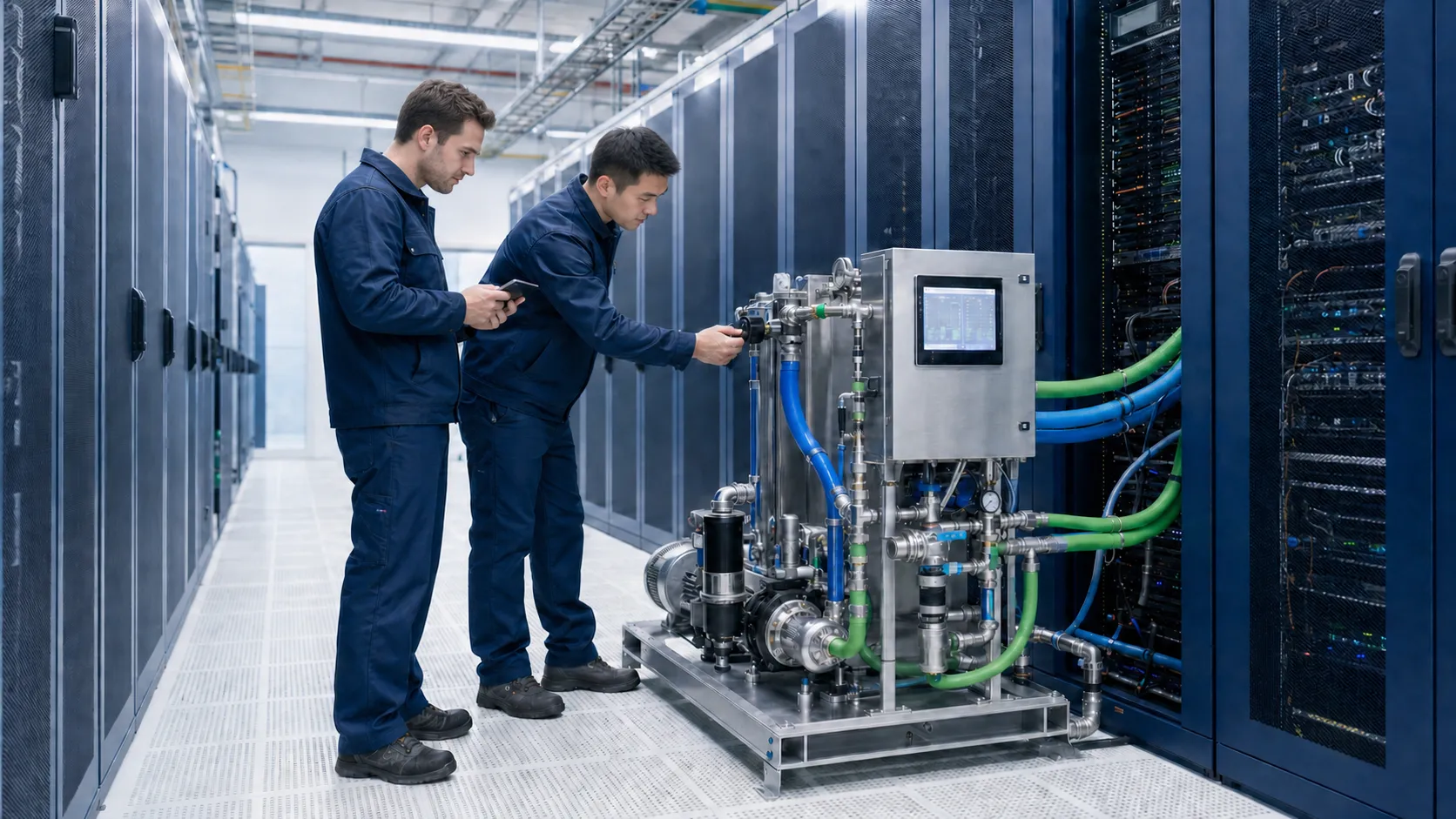
AI Rack Liquid Cooling Integration Project
Use this module for a verified project: rack load, facility water, secondary-loop target, architecture, responsibility boundary, validation method and measurable result. Until authentic evidence is approved, label generated visuals as application concept renderings.
FREQUENTLY ASKED QUESTIONS
Data Center Liquid Cooling FAQ
What is data center liquid cooling?
Data center liquid cooling transfers heat using a controlled liquid loop. Depending on the architecture, coolant may serve server cold plates, rear-door heat exchangers or another liquid-assisted heat-removal device.
What is direct-to-chip liquid cooling?
Direct-to-chip cooling uses cold plates attached to processors, accelerators or other high-heat components. A secondary loop distributes controlled coolant to those cold plates.
What is a coolant distribution unit or CDU?
A CDU is the control boundary between a facility-water system and a secondary technology cooling system. Typical functions can include heat exchange, pumping, filtration, temperature and pressure control, sensors, alarms and communications.
Why separate facility water from the server loop?
Separation helps protect IT equipment from facility-water quality, pressure and hydraulic variation while allowing the secondary loop to use controlled coolant conditions.
Does EVLINK supply cold plates, rack manifolds or complete CDUs?
The current page presents a project-specific engineering scope. The exact EVLINK hardware, purchased subsystems and responsibility boundary must be confirmed in writing after requirements review.
What information is required to start a project?
Provide IT load, rack density, server requirements, coolant temperatures, flow and pressure, facility-water data, redundancy target, footprint, electrical supply, leak strategy and communication requirements.
Can the cooling system connect to BMS or DCIM?
A monitoring interface can be reviewed around the selected controller and customer protocol. Required data points, alarms, ownership and protocol—such as Modbus, BACnet or SNMP—must be confirmed for the project.
START YOUR PROJECT
Planning Liquid Cooling for an AI or High-Density Data Center?
Share the IT load, rack density, facility water, coolant targets, flow, pressure, redundancy, installation space and monitoring requirements. EVLINK will review the project and define the appropriate engineering scope.