Book Appointment Now



Choosing a PTC Coolant Heater for a Battery Thermal Management System
A practical interface and procurement checklist for selecting a PTC coolant heater for a battery thermal management system.
When selecting PTC coolant heaters, battery thermal management system suppliers must not base their decisions solely on the rated power in kilowatts (kW). The heater must be compatible with the vehicle’s available voltage, the installed cooling circuit, the control architecture and the specific heating task. Equipment that appears suitable in a product catalogue may require the replacement of connectors, the adjustment of control interfaces or further hydraulic system assessment prior to actual integration.
For electric bus or lorry projects, the first step is to clarify one key question: what functions does the battery system actually need to fulfil? Under what operating conditions? Before approving samples, it is essential to require the heater supplier to validate the proposed configuration based on these operating conditions.
Define the heating task before determining the rated power
Consult the battery supplier regarding the applicable temperature range and operating limitations. Clarify the intended use of the heater: is it for battery preheating, cabin heating, or a combination of both? Record the battery’s initial state, environmental conditions, available heating duration and the vehicle’s operating mode. For example, the available power budget whilst the vehicle is parked and connected to a charging point may differ from that whilst the vehicle is in motion.
Never estimate the expected heating time based solely on the power rating stated on the heater’s nameplate. Battery mass, initial temperature, heat loss, coolant distribution and available electrical power will all affect the final system performance. Heating targets and test boundary conditions should be agreed upon jointly with the battery team and the vehicle integration team.
Matching Voltage and Power at the Same Operating Point
Obtain the minimum and maximum supply voltages for the vehicle under various relevant operating modes. Compare these values with the operating limits of the selected heater configuration; do not rely solely on nominal platform voltages such as ‘400 V’ or ‘800 V’. Request that suppliers specify the voltage, coolant inlet temperature and flow rate conditions under which their stated heating output power was measured.
System integrators must also confirm the electrical power budget. If other vehicle loads share the same power supply system, the rated output power stated on the heater’s nameplate does not represent the power actually available for heating at any given moment. Furthermore, the selection of cables, connectors and protective devices must comply with the approved vehicle electrical design.
Check the Installation of the Cooling Circuit
The heater is merely one resistive element in the cooling circuit; the circuit may also contain a water pump, hoses, valves, cold plates and other heat exchangers. It is essential to request pressure drop data from the supplier for this heater under specific coolant type, temperature and flow rate conditions. Compare the requirements of the entire circuit with the applicable performance curve of the pump.
If the circuit contains parallel branches, the total flow rate of the pump will differ from the flow rate in the heater branch. It is necessary to clarify how the flow rate through the selected branch is measured under various operating modes. For cold start conditions, consult the pump and heater suppliers to confirm which data applies to the selected coolant and initial temperature conditions.
Determining Control Interfaces
High-voltage heating power supplies should be kept separate from low-voltage control power supplies. Obtain connector diagrams, power requirements and interface information for the selected model. Different configurations may utilise CAN communication or other control methods; do not assume that all heaters use the same interface.
Clarify who issues the heating request, which signals are used to confirm the actual operating status, which controller provides feedback on operating limits, and how the vehicle should respond in the event of a communication failure. Simply sharing a CAN bus does not constitute a complete control strategy. It is essential to confirm in writing the signal definitions, software versions and diagnostic procedures for the proposed project.
Use one shared interface record
| Review item | Information the system supplier should agree with the heater supplier |
|---|---|
| Heating duty | Heat consumer, initial condition, target and available time |
| Electrical supply | Minimum and maximum voltage and available power in each mode |
| Coolant loop | Fluid, concentration, heater branch flow, pressure and inlet conditions |
| Control | Request owner, interface, feedback, restrictions and fault handling |
| Installation | Released drawing, connectors, mounting, orientation and service access |
| Verification | Hardware and software revisions, test conditions and acceptance criteria |
| Procurement | Sample configuration, documentation, change communication and quantity plan |
Mark missing parameters as ‘to be determined’. Suppliers cannot validate the entire system configuration based solely on an incomplete list of assumptions.
Validation of Samples in Installed Systems
Prior to the commencement of testing, the relevant teams should reach a consensus on the initial state of the battery and coolant, sensor locations, operating modes and acceptance criteria. A uniform time reference should be adopted when recording heater requests and feedback, relevant power supply conditions, coolant inlet and outlet temperatures, and heater branch flow rates.
Evaluate steady-state heating processes and the transition between different vehicle operating modes. If measured data deviates from expectations, retain the raw data and verify the interfaces and test boundaries in collaboration with the relevant suppliers. Under no circumstances should protective functions be bypassed to achieve ideal results; any fault injection operations must be incorporated into authorised test procedures.
Clarification of Approved Production Configurations
Upon acceptance of the sample, the confirmed part numbers, drawing versions, connector layouts, applicable control interfaces and any customer-specific options should be documented. The system manufacturer and the heater supplier should agree on a change communication mechanism and clarify which changes require additional engineering reviews.
Demand forecasts and target delivery schedules may serve as a reference for procurement; however, for specific orders, actual production capacity, lead times and commercial terms must be confirmed. Approval of a sample does not imply that other hardware or software versions are equivalent to it.
Discuss your BTMS (Battery Thermal Management System) heating requirements with EVLINK
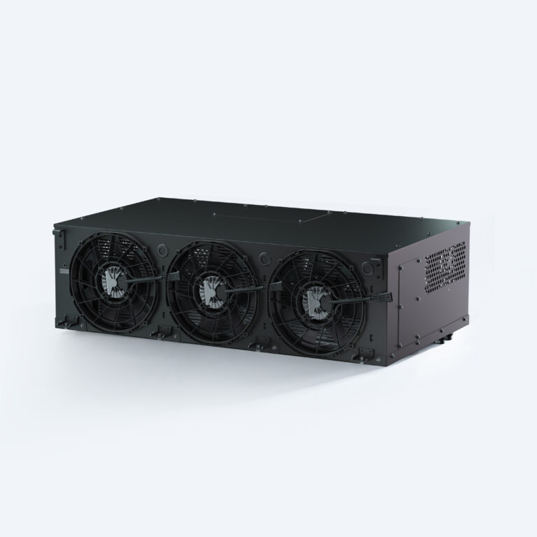
EVLINK’s High-Voltage Coolant Heater Series can serve as a starting point for your evaluation of electric vehicle heating projects. Please provide the following information: application scenario, required power, full voltage range, coolant state, available space and control interface. If you plan to replace an existing heater, please provide its officially released drawings and the boundary conditions of the current system.
Submit your project requirements so that we may further discuss heater configurations, relevant technical documentation and matters that still require validation at the vehicle level.