Book Appointment Now


Braking Resistor Types and Installation Guide
Previously, we received a request for quotation containing just one specification: ‘120 kW, air-cooled or liquid-cooled, please provide a quote.’ We replied with six questions, but the client assumed we were deliberately stalling. Three weeks later, he finally provided the answers: the vehicle had no chopper output, there was no spare coolant flow at the installation site, and the equipment was to be installed in a sealed compartment beneath the vehicle. Although the power rating of ‘120 kW’ was correct, virtually all other pre-defined conditions were inaccurate.
This situation is all too common. Orders for braking resistors often run into problems before installation even begins—problems that arise at the desk: people treat a single power rating as a complete specification, whilst leaving the actual installation conditions to be ‘resolved on the spot’ once the vehicle is on site. This guide first clarifies three core concepts, followed by a checklist recommending that you confirm these details in writing before placing an order. Where parameters apply only to specific models, this guide will indicate this and leave the values blank; for the vehicles covered in this article, providing generic torque, cable or temperature values would likely render them unsuitable in half of the cases.
Concept 1: Heat equals power multiplied by time
Let us consider a specific example, as the abstract concept of ‘kilowatts’ often obscures the practical issues. Our HVH-R1402 model has a rated power of 140 kW and can operate continuously for 20 minutes. If operated at this power, it must continuously dissipate 168 MJ (i.e. 46.7 kWh) of heat within 20 minutes; otherwise, the resistor will fail due to overheating before the descent is complete.
The same logic applies in our selection guide when dealing with smaller-scale operating conditions. An 18-tonne coach travelling at 30 km/h on a 7 per cent gradient requires approximately 103 kW of braking power, which generates around 34 kWh of heat over 20 minutes. For the HVH-R1402, 103 kW represents only about three-quarters of its rated power, leaving a margin of safety. However, if we were to use equipment designed solely for short, intermittent braking, the same 103 kW operating condition would be an entirely different matter—because the rated parameters for such equipment are based on the assumption that there will be intermittent rest periods, whereas on long downhill stretches in mountainous terrain, the resistor has absolutely no opportunity to rest.
Conventions in the industrial drive sector can easily lead one to fall into this trap. If, within a two-minute cycle, braking lasts for several seconds, this constitutes a high-load operating condition. On long downhill gradients (such as those on bus routes), the braking process continues throughout the entire descent, at which point the load factor effectively reaches 100 per cent. Any rated specifications based on the assumption of ‘intermittent rest periods’ will fail under such operating conditions; such failure may appear to be a product fault, but is in fact caused by inappropriate specification selection.
Therefore, the primary consideration is not whether to choose air-cooling or liquid-cooling, but to clearly define the ‘longest braking condition’—which must specifically include three dimensions: peak power, continuous power and duration (measured in minutes). All three pieces of data are indispensable. If a supplier only enquires about one of these during communication, it indicates that their requirements analysis has not been completed.
Concept 2: Cooling is not ‘purchased’, but ‘borrowed’
A resistor cannot cool itself; it must ‘borrow’ a cooling system, the specific form of which depends on the conditions under which it is ‘borrowed’.
Air-cooled units rely on airflow. Whilst this may sound ‘free’, the situation is quite different when the unit’s installation location is taken into account. For many years, drive system manufacturers have emphasised this trade-off: adding a fan can roughly double the available power, as the moving air takes on the task of heat dissipation; conversely, if airflow is lost, the rated power will be significantly reduced. Whether housed in an enclosed compartment, tightly squeezed between other equipment, or installed in a location where hot air cannot escape, these circumstances render the power ratings in the product manual invalid – with actual performance already significantly compromised even before the vehicle is started.
Liquid-cooled units, on the other hand, rely on the coolant circulation circuit. As most electric buses and lorries are already equipped with such circuits, liquid cooling is a particularly well-suited solution for these vehicle types. However, ‘borrowing’ the circuit requires correct integration: the flow rate at the resistor connection must match the circuit conditions under actual driving conditions; the pipework layout should avoid sudden restrictions in flow resistance; and, furthermore, a means must be provided to purge air from the pipework following maintenance. Taking our HVH-R1402 model as an example, to maintain a power output of 140 kW for 20 minutes, the flow rate at its DN32 connection must reach at least 172 L/min. This figure applies solely to the performance of this specific model under specific operating conditions and is not universal to all liquid-cooled resistors.
Concept 3: Switching and dissipation are two independent functions
The function of a resistor is to ‘dissipate’ energy; it cannot connect to the DC bus on its own. This ‘switching’ task is performed by a chopper; the chopper connects the resistor to the DC bus in a pulsed manner and uses pulse width to regulate the average power.
Some vehicle controllers incorporate a chopper output function, whilst other platforms lack any switching mechanism whatsoever. This critical difference directly determines procurement requirements, yet is often only discovered at a late stage of the project. If only a resistor is procured for a platform lacking a switching function, the component will be unable to perform the braking function; conversely, if a chopper is purchased in addition to a controller that already has a chopper function, this results in redundant procurement.
Given the differences between platforms in this regard, we offer three configuration options. For controllers that already possess switching functionality, a pure resistor unit is sufficient. For platforms requiring the addition of braking functionality, if the switching components require separate installation space and cooling solutions, the ‘resistor + standalone chopper’ combination is more suitable; whereas if the platform wishes to procure the braking circuit as a single integrated unit, the ‘integrated chopper and braking resistor unit’ is the better choice. The distinction between the two lies in ‘compatibility’ rather than ‘quality’; compatibility depends on the vehicle’s existing configuration. Such issues should be clarified at the outset of the project (i.e. in the first communication email), rather than being discovered only during the commissioning phase.
The classification method in the product catalogue should not be the basis for your order decision
Industrial catalogues are typically categorised by the type of resistive element, such as wire-wound (coils), ribbon-wound (flat strips) or sealed aluminium casing. Whilst these classifications reflect actual manufacturing processes, they are of limited value for procurement purposes, as the resistive elements are encapsulated within the unit and cannot be replaced once installed.
The classification that truly influences procurement decisions is the distinction between ‘standard catalogue products’ and ‘customised products’. The specifications of resistors in standard catalogues are fixed; custom resistors, on the other hand, are specifically wound to match the DC bus voltage range (i.e. the ‘voltage window’) of a particular platform. Take our HVH-R1402 model as an example: it has a resistance value of 2.24 ohms and is suitable for a DC voltage range of 450 V to 850 V. As power is proportional to the square of the voltage, the instantaneous power at 450 V is approximately 90 kW; whereas at 850 V, the instantaneous power can reach approximately 323 kW—a difference of 3.57 times. If resistance tolerance is taken into account, the difference widens further: at a resistance of 2.016 ohms and a voltage of 850 V, the current corresponding to the power is approximately 422 A; whereas at a resistance of 2.464 ohms and a voltage of 450 V, the power drops to approximately 82 kW. Please ensure that this voltage range (i.e. the upper and lower limits) is clearly specified in writing.
Before carrying out any fixed installation, please ensure you obtain the relevant technical data.
This section constitutes the core operational part of this guide. Never place an order based solely on a summary of the data sheet. Please ask the supplier to complete the items in the table below for the specific model you are purchasing, and retain the completed form with your order. For the HVH-R1402 model, where relevant parameters have been published, these will be listed directly; where parameters depend on the interface specifications of the specific model, this will be stated—we will never arbitrarily fabricate substitute values.
Installation and mechanical structure.
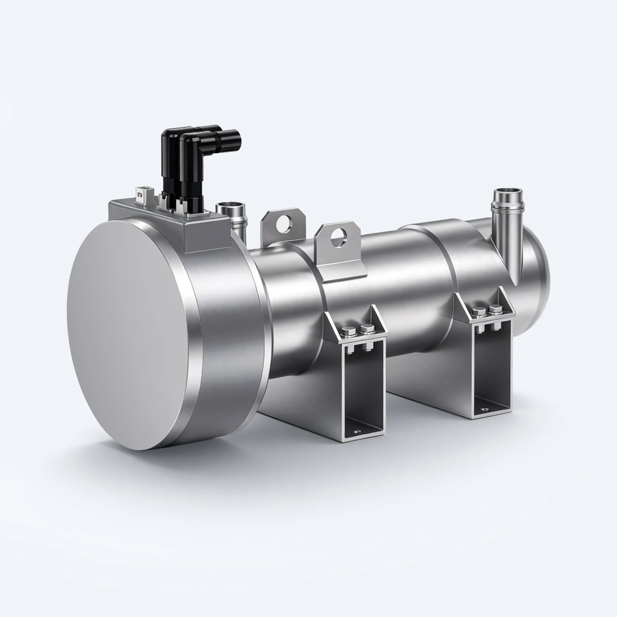
Please request the following information: installation footprint and external dimensions, equipment weight, permitted installation orientations, bolt layout and hole diameters, tightening torques for installation fasteners, and space requirements for maintenance and servicing; you should also confirm whether the surrounding materials possess heat resistance. Taking the HVH-R1402 as an example, its published dimensions are 659 × 232 × 253 mm, and it weighs approximately 40 kg; it supports horizontal bracket mounting or suspended installation; the enclosure protection rating is IP6K9K. Regarding the tightening torques, bolt specifications and clearance requirements for specific installation schemes, please ensure you refer to the interface specifications for the model you have purchased; do not apply generic tables.
Electrical interfaces.
Please request the following information: bus voltage range and resistance (including values at both ends and tolerances), rated current, connector type, cable entry method, recommended cable specifications and terminal tightening torque, as well as the required electrical clearance and creepage distance. For the HVH-R1402, the rated voltage range is 450 to 850 V DC; the cold resistance is 2.24 Ω (tolerance ±10 per cent); and the rated current is 250 A. Cable specifications, terminal tightening torques and clearance requirements all depend on the interface specifications for the specific model; please verify these for the exact product model you have purchased. Regardless of the specific specifications, one cabling principle always applies: resistance cables should be kept as short as possible within the constraints of the layout and kept away from signal cables.
Cooling interface.
Please request the following information: the dimensions and type of the coolant interface, the type of coolant required by the design, the flow rate requirements under rated operating conditions, the coolant temperature limits, and the venting (drainage) location of the cooling circuit. Taking the HVH-R1402 as an example, its interface size is DN32, and the coolant used is a mixture of 50 per cent water and 50 per cent ethylene glycol; when operating at 140 kW for 20 minutes, the flow rate at the interface must reach at least 172 L/min. For flow rate requirements under other operating conditions, please refer to the interface specifications for this model. We have documented issues arising from incorrect selection: estimating flow rate based solely on the pump’s performance curve (rather than actual measurements at the connection point) often leads to discrepancies. For example, in one application, due to the use of a shared pump, excessively long pipework and two sharp bends, the actual flow rate was only about half of the required amount, whilst the resistive components in the system were mistakenly identified as the ‘culprits’ causing the circuit failure. Furthermore, residual air remaining in the circuit following maintenance can cause the same damage without any audible warning.
Thermal protection and safety circuits.
In addition to enquiring about the type and accuracy of the temperature sensor, attention should also be paid to key details in the data sheet that are often overlooked: alarm, derating and cut-off temperature thresholds; response times following an overtemperature event or interlock disengagement; the controller’s operational logic upon interlock disengagement; system recovery procedures; and the fault codes or signals received by the vehicle. The HVH-R1402 is equipped with an NTC 5K sensor with an accuracy of ±1 per cent and features a high-voltage interlock circuit. Specific temperature thresholds, response times, interlock logic, recovery conditions and fault definitions must all be confirmed by referring to the interface specifications for this model. If the sensor is not connected correctly, cooling issues will directly result in a system fault (rather than merely triggering an alarm); if the interlock circuit is bypassed, the potential hazard of an incompletely mated connector will not be detected in a timely manner until arcing occurs.
Verification evidence.
Suppliers are required to provide load test data under rated operating conditions (rather than merely a rated value) and to confirm which production tests and type tests this model has passed. The HVH-R1402 has been validated through 25 production tests and type tests. If the supplier is unable to provide test evidence under the operating conditions you require, please list this as a ‘pending issue’; under no circumstances should you leave this to be addressed after delivery.
A general principle regarding the table is that a blank row does not indicate a value of zero, nor does it imply that it can be arbitrarily set to a ‘standard value’. There is still work to be done; where there is a change in the installation method, subsequent processes should be put on hold for the time being.
Installation Process: Four ‘Stages’, Rather Than a Set of Operating Instructions
This guide does not provide step-by-step installation instructions—such instructions would be unfounded without specific model and interface specifications. Instead, it sets out a series of ‘stages’, which a comprehensive installation plan must pass through in sequence.
Checkpoint 1: Data Pack.
All relevant entries must be completed in full for the specific model; where items remain outstanding, the person responsible and the deadline for completion must be clearly specified. If Checkpoint 1 is not passed, no order may be placed.
Second Checkpoint: Cooling System Verification.
For liquid-cooled units, the flow rate must be measured at the resistor interface whilst the circuit is fully operational, rather than relying solely on the pump’s performance curve. For air-cooled units, an inspection must be carried out at the actual installation location to ensure adequate airflow and that clearance requirements are met (the vehicle must be in a sealed, operational state at this stage). If cooling conditions do not meet the standards, the circuit design or installation plan must be adjusted first.
Stage Three: Installation, Wiring and Safety Circuit Verification (under low load).
The unit must be installed in a location that facilitates maintenance; wiring must comply with the model-specific connection specifications; prior to braking operations, the controller must be able to read temperature data correctly; the interlock circuit must remain conductive; and the switching operation of the chopper must be verified under low load conditions. Should any of these requirements be unmet, the installation process must be halted at this stage.
Stage Four: Initial Braking Test on the Vehicle (requiring full monitoring).
Focus on monitoring temperature changes during operation, flow rates in the actual circuit, and whether the performance of the safety circuit matches the expectations set out in the data package. If any of these indicators fail to meet the requirements, the vehicle must not be permitted to enter mountain roads for field testing.
Four ‘Work Halt’ Signals
If any of the following situations arise, please stop the installation immediately and do not secure the device in place:
Firstly, there are critical omissions in the data package that affect installation, and no one is responsible for rectifying them. Carrying out installation blindly in the absence of information often leads to on-site personnel arbitrarily fabricating parameters such as torque, cable specifications or temperature limits.
Secondly, the cooling solution is based solely on the performance curve of the water pump or the fan specification sheet, rather than on actual measurement data taken at the installation site. Performance curves do not equate to actual flow rates, nor do fan rated parameters accurately represent actual airflow conditions within an enclosed enclosure.
Thirdly, the switch control scheme remains unclear. There is currently no written confirmation as to whether the controller is equipped with a chopper output function; consequently, you are uncertain whether you will ultimately need to procure one or two components.
Fourthly, the resistance parameters provided are based solely on a single power value, without specifying the bus voltage range (bus window). In our modelling, a particular resistance may appear suitable under one operating condition but may be entirely unsuitable under another; differences in instantaneous power can even exceed threefold. Before finalising the product model, it is essential to clarify the bus voltage range and the operating parameters at both ends.
Information you need to provide
If you would like us to recommend a specific model (rather than simply providing a product catalogue page), please supply the following basic information and known parameters from the datasheet: the bus voltage range, continuous power and maximum braking duration, whether the controller already features a chopper output function, the coolant flow rate at the installation location, as well as the installation space and its airflow or coolant supply conditions. You may request that we complete a full product data sheet for the HVH-R1402 series (including the parameters specified in this guide that must be determined based on specific interface specifications). We will evaluate this based on the information you provide, in conjunction with the specifications of the HVH-R1402 (2.24 ohms, 450 to 850 V DC, 140 kW continuous power (for 20 minutes), IP6K9K protection rating, operating temperature range of –40 to +85 °C, and 25 tests passed); should another model be more suitable for this platform, or should a resistor not be required at all, we will inform you accordingly. The minimum order quantity for this product is 10 units, with a lead time of one week. For further product details, please refer to our braking resistor page.
Frequently Asked Questions (FAQ)
Can I select a braking resistor based solely on the power parameters given in the product catalogue?
No. Without information such as duty cycle, busbar voltage range and cooling solution, the power parameters alone do not constitute a complete specification. Two units with the same rated power (in kilowatts) may fail for different reasons: some may overheat due to a lack of air circulation, others due to insufficient coolant, whilst others may fail to operate correctly due to incorrect switching.
Do I need a brake chopper, or is a braking resistor sufficient?
Both functions are essential, but they do not necessarily have to exist as separate components. If your controller already features a chopper output function, then a pure resistor unit will suffice. If the vehicle lacks the necessary equipment to connect the resistor to the busbar (i.e. to switch it on and off), an additional chopper will be required, or a unit with integrated chopper functionality should be selected. Please ensure that the switching scheme is clarified in advance and confirmed in writing.
Can air-cooled braking resistors be used in electric buses?
They may be used for short, intermittent braking in a well-ventilated installation environment. However, they are not suitable for continuous braking on long downhill gradients or when installed in enclosed spaces with poor air circulation. This constitutes a mismatch in cooling methods, which will lead to overheating issues that cannot be resolved simply by replacing the resistor itself.
Can I replace an air-cooled resistor with a liquid-cooled one?
This is possible provided the vehicle can supply a fully functional coolant circulation circuit: the installation point must have sufficient flow rate, a reasonable pipework layout, and a means of venting (to remove air from the circuit). Without a complete circulation circuit, a liquid-cooled resistor is effectively equivalent to an air-cooled resistor with an additional interface. Please ensure the circulation circuit is verified before placing an order.
What coolant flow rate is required for a braking resistor?
This depends on the specific product model and operating conditions; any accurate answer must take both of these factors into account. Taking our HVH-R1402 model as an example, to maintain a continuous power output of 140 kW for 20 minutes, the coolant flow rate at the DN32 connection must be at least 172 L/min. For other models or operating conditions, the specific flow rate should be determined by referring to the connection specifications for that model, with the actual measured value at the connection point taking precedence.
Why does this guide not provide parameters such as torque, cable specifications or temperature thresholds?
These values depend on the specific model and its interface specifications; using generic values may not be applicable to other models. Please request written specifications from your supplier for the specific model you have purchased (i.e. the specific product number). It is far safer to leave these fields blank in technical documentation than to directly apply values from other models—leaving them blank is obvious, whereas applying values can easily lead to the mistaken assumption that the data is complete.