Book Appointment Now


ENGINEERING | SYSTEM DESIGN & INTEGRATION
EV Thermal Management System Design & Integration
System-level engineering for battery cooling, high-voltage coolant heating, electric compression, coolant circuits, high- and low-voltage interfaces and CAN control.
EVLINK helps OEM teams convert platform data, duty cycles and thermal targets into a reviewable architecture, component configuration, interface definition and validation plan. The objective is not simply to select parts, but to make the complete thermal system work together.
Architecture
Loops and operating modes
Integration
Mechanical, HV/LV and CAN
Validation
Proof before release
WHY SYSTEM ENGINEERING MATTERS
A Thermal System Can Fail Even When Every Component Works
Most integration problems occur between components. System design exposes those risks before tooling, prototypes and validation become expensive.
01
Parts Selected Before Loads
Components are chosen before the real duty cycle, charging load and ambient conditions are understood.
02
Disconnected Thermal Loops
Battery, power electronics, cabin and coolant circuits are designed without clear ownership or priorities.
03
Interfaces Defined Too Late
Mounting, ports, connectors, HV/LV supply and CAN signals change after the prototype is built.
04
Control Modes Not Agreed
Start-up, preconditioning, high-load, charging, derating and fault responses are incomplete.
05
Validation Without Criteria
Tests begin before limits, measurements, conditions and acceptance rules are agreed.
SYSTEM DESIGN SCOPE
Six Workstreams in EV Thermal Management System Integration
Each workstream creates reviewable engineering outputs and reduces late-stage change risk.
01
Thermal Load Analysis
Review battery, charging, traction, auxiliary, cabin and environmental loads.
- Steady and transient loads
- Heating and cooling targets
- Worst-case operating conditions
02
Thermal Architecture
Define cooling, heating and refrigerant loops plus component and control ownership.
- Loop and component map
- Operating mode concept
- Preliminary protection strategy
03
Component Sizing
Select candidate BTMS, HVCH, compressor and controller configurations.
- Voltage and power fit
- Flow and temperature basis
- Package and environment review
04
Mechanical Integration
Define envelope, mounting, orientation, routing, vibration and service access.
- 2D / 3D review
- Mounting interfaces
- Coolant port access
05
Electrical & CAN Integration
Align HV/LV, connectors, signals, states, commands, faults and diagnostics.
- Interface responsibility
- CAN signal review
- Fault-handling concept
06
Validation Planning
Connect the design assumptions to measurable test conditions and approval criteria.
- Prototype test matrix
- Acceptance criteria
- Change and issue tracking
INTEGRATED ARCHITECTURE
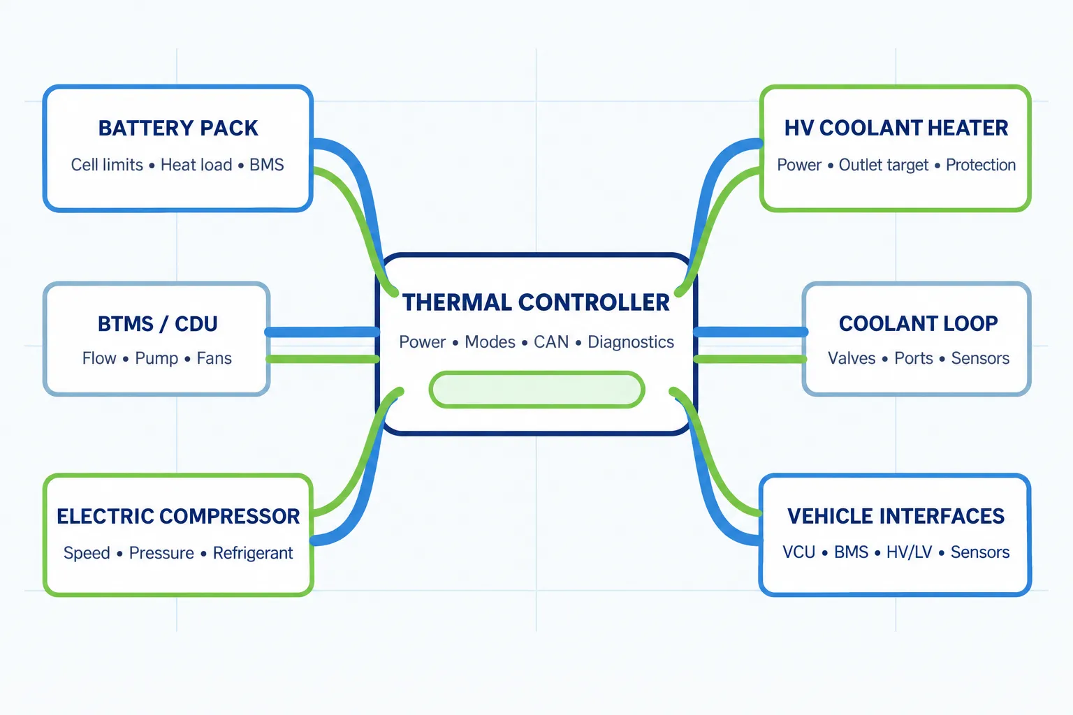
Connect Every Thermal, Electrical and Control Interface
The architecture defines what each component does, which loop it belongs to, what commands it receives, what feedback it returns and how the system responds across normal and faulted operation.
- Battery pack and BMS limits
- BTMS or coolant distribution unit
- High-voltage coolant heater
- Electric compressor and refrigerant circuit
- Pumps, valves, fans and sensors
- Thermal controller, VCU and CAN communication
DESIGN INPUTS
Eight Factors That Drive Thermal Architecture Decisions
A reusable platform architecture still needs application-specific data. These factors shape component selection and control strategy.
01
Duty Cycle
Route, payload, grade, working cycle, charging, idle time and seasonal operation.
02
Thermal Targets
Battery, coolant, cabin and electronics temperature limits plus transient response.
03
Environment
Ambient range, altitude, dust, crop debris, vibration, washdown and airflow.
04
Packaging
Installation envelope, orientation, access, hose bends, cable routing and maintenance.
05
Energy Use
Heating and cooling demand, parasitic power, preconditioning and range impact.
06
Control Ownership
VCU, BMS and thermal controller responsibilities, states, limits and diagnostics.
07
Safety & Protection
HV interlock, insulation, temperature, pressure, current and fault response.
08
Validation
Customer standards, target markets, test conditions, records and release criteria.
INTERFACE DEFINITION
Translate the Architecture into Clear Engineering Interfaces
The interface matrix gives engineering, suppliers and purchasing one shared view of responsibilities and deliverables.
Interface Area
What Must Be Defined
Typical Engineering Output
Risk if Missed
Mechanical
Envelope, mounting, orientation, vibration and service access
2D/3D drawing and installation interface
Interference, fatigue or poor maintainability
Coolant / Refrigerant
Fluid, ports, flow, pressure, routing, venting and leak control
Circuit and connection information
Low performance, cavitation, trapped air or leaks
High / Low Voltage
Supply, connectors, wiring, interlock, current and protection boundary
Electrical interface definition
Unsafe connection, nuisance shutdown or component damage
Signals & CAN
Commands, feedback, states, limits, faults, timing and diagnostics
CAN communication documentation
Conflicting control, unstable modes or weak diagnostics
Vehicle Operation
Start-up, charging, high load, derating, shutdown and service
Operating mode and validation matrix
Unexpected behavior in real duty cycles
CONTROL STRATEGY
Design Around Real Operating Modes, Not One Rated Point
Every mode should have clear entry conditions, priorities, targets, limits, outputs and fault responses.
01
Power-Up & Self-Check
Confirm communication, sensor plausibility, protection status and component availability.
02
Cold-Start Preconditioning
Coordinate heating, pumps and battery limits before drive or charging.
03
Normal Driving / Working
Maintain temperatures while balancing energy use and comfort or auxiliary loads.
04
High-Load Operation
Respond to sustained grade, haul, PTO, hydraulic or high-compute loads.
05
Charging Thermal Control
Manage battery temperature during depot, opportunity or fast charging.
06
Derating, Fault & Shutdown
Define safe limits, fallback behavior, diagnostics, cooldown and restart conditions.
ENGINEERING WORKFLOW
A Gated System Design and Integration Process
Each gate should close specific technical questions before the project moves forward.
01
Collect Requirements
Gather platform, battery, thermal, electrical, control, environment and timing data.
02
Calculate & Define Loads
Establish operating cases, heat loads, heating demand and critical transients.
03
Build the Architecture
Define loops, products, sensors, operating modes and responsibility boundaries.
04
Select & Size Components
Narrow the BTMS, heater, compressor and controller configuration.
05
Complete Interface Review
Review drawings, ports, HV/LV, connectors, CAN and installation access.
06
Prototype Integration
Support sample installation, commissioning and initial operating-mode checks.
07
Validate & Optimize
Compare results with criteria, investigate issues and update the design.
08
Freeze for Production
Approve configuration, change status and production delivery documentation.
PROJECT INTAKE
Information Required for EV Thermal System Design
Reliable input data shortens the concept phase, exposes risks early and helps EVLINK prepare a technically relevant proposal.
- Platform type, application and operating mass
- Battery capacity, chemistry, layout and BMS limits
- Route, duty cycle, workload, charging and idle periods
- High- and low-voltage levels
- Cooling and heating targets
- Minimum and maximum ambient conditions
- Coolant, refrigerant, flow and pressure requirements
- Installation envelope, orientation and service space
- Connector, wiring and HV interlock requirements
- VCU / BMS / CAN protocol and control ownership
- Environmental and vibration requirements
- Target standards, prototype timing and annual demand
ENGINEERING DELIVERABLES
What Your Team Receives from System Design & Integration
The final document set depends on project scope, selected products and development phase.
01
System Requirement Summary
Agreed loads, environment, interfaces, limits and assumptions.
02
Thermal Architecture Proposal
Cooling, heating, refrigerant, power and control relationships.
03
Component Selection & Sizing
Candidate models and technical basis for the proposed configuration.
04
2D / 3D Drawings
Product geometry for packaging and installation review.
05
Mechanical & Coolant Interfaces
Mounting, orientation, ports, fluids, flow and routing inputs.
06
Electrical & Connector Data
HV/LV supply, wiring, connectors, interlock and protection inputs.
07
CAN Communication Document
Commands, feedback, operating states, faults and diagnostics.
08
Prototype & Validation Plan
Samples, test conditions, measurements and acceptance criteria.
09
Release Documentation
Approved configuration, changes and production delivery information.
APPLICATION INTEGRATION
Adapt the System Architecture to the Real Platform
The engineering method is repeatable, but loads, interfaces and validation differ by application.
06
Data Center Liquid Cooling
Separate flow, pressure, redundancy and monitoring requirements.
RELATED PRODUCTS
EVLINK Components for Integrated Thermal Architectures
Final product selection follows the complete system requirement, not the product name alone.
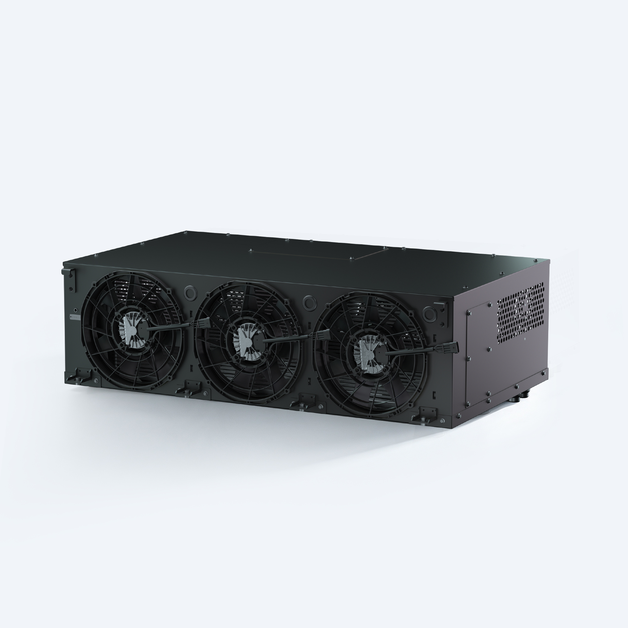
01 | Battery Thermal Management System
Battery liquid cooling and heating support configured around duty and charging.
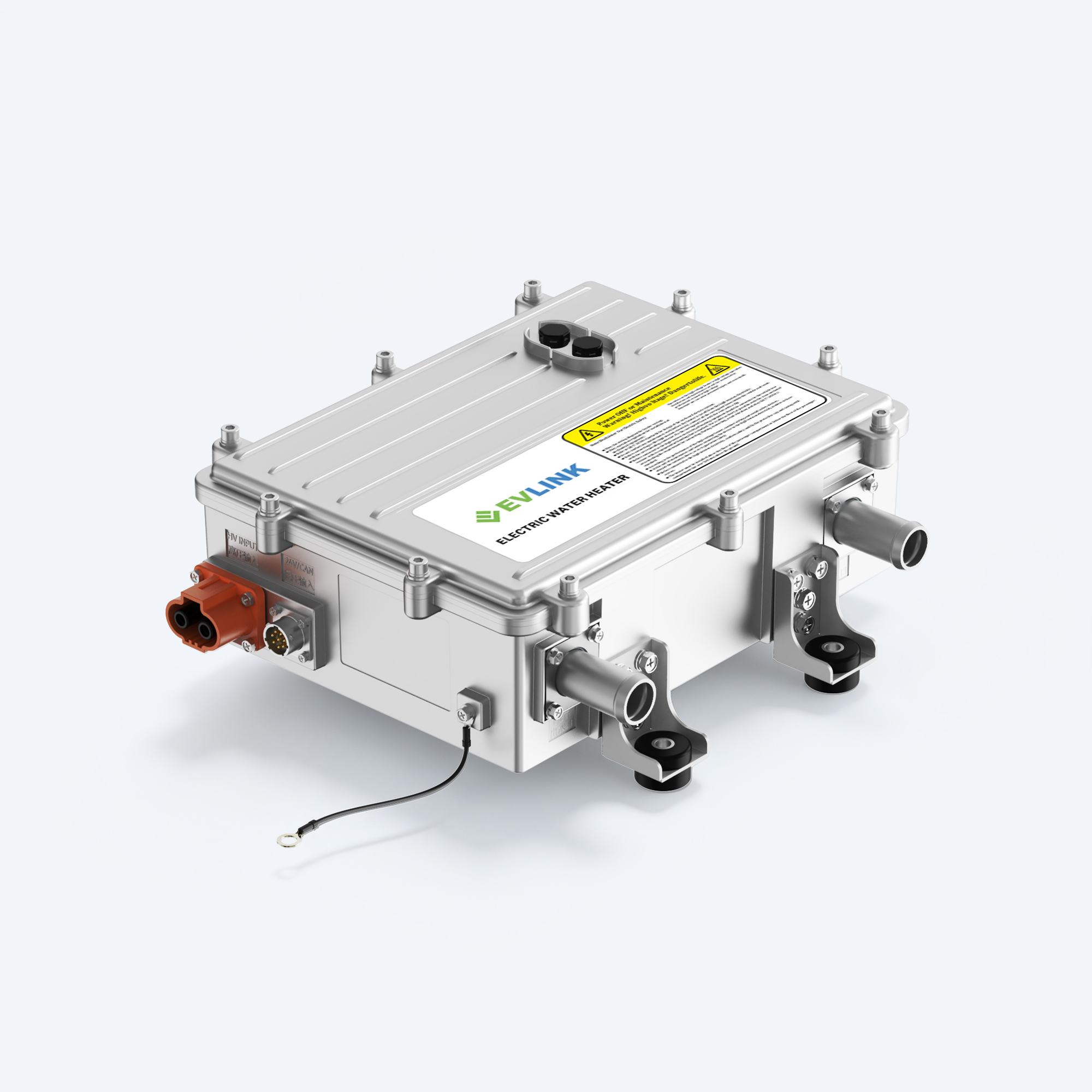
02 | High Voltage Coolant Heater
Controlled coolant heating for battery conditioning and related thermal loads.
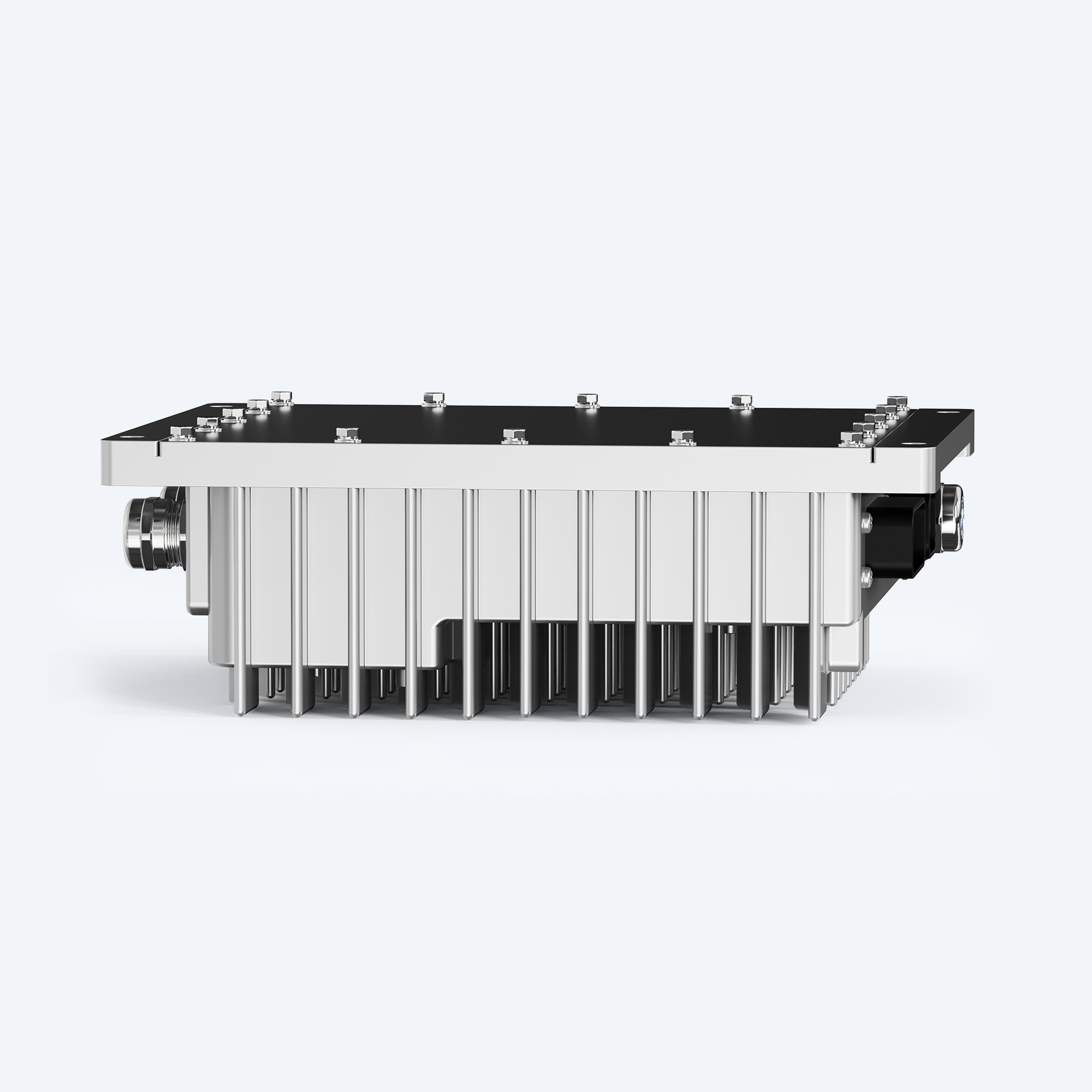
03 | Three-in-One Controller
Integrated thermal power, operating modes and CAN communication.
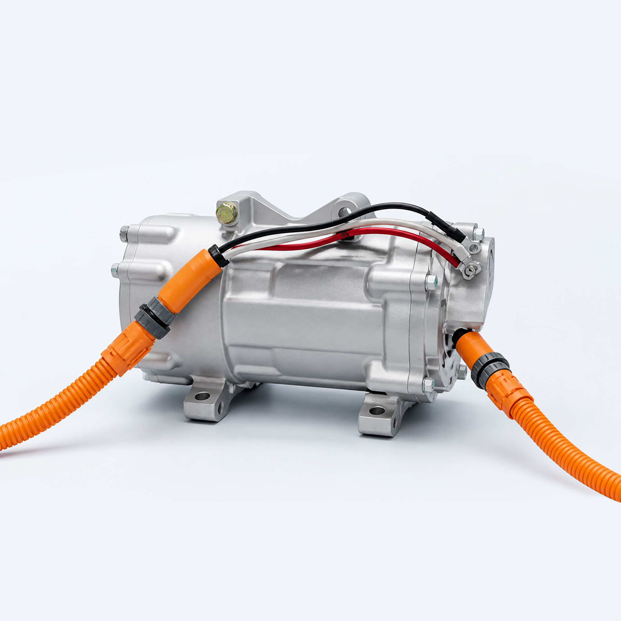
04 | Electric Compressor
Active refrigerant compression for project-specific cooling circuits.
ENGINEERING PROOF
Replace Claims with Reviewable Project Evidence
The delivery ZIP includes matching system, CAN engineering and validation images. Replace placeholders only with permission-cleared material and accurate captions.
01
System Architecture Review
Use an authentic CAD, installation or system-review image with a factual caption.
02
CAN & Interface Integration
Show real communication, electrical or commissioning work and approved details.
03
Prototype Validation
Show actual test equipment, conditions and model-specific validation evidence.
FREQUENTLY ASKED QUESTIONS
EV Thermal Management System Design FAQ
What is EV thermal management system design and integration?
It is the process of defining thermal loads, cooling and heating loops, products, mechanical and coolant interfaces, HV/LV connections, CAN control, operating modes and validation criteria as one coordinated system.
Why is system design needed if the components already have specifications?
Component specifications describe individual operating limits. System design verifies whether the components, surrounding loops, controls and real duty cycle work together at platform level.
Which products can be included in the architecture?
Depending on the project, the architecture may include a battery thermal management system, high-voltage coolant heater, electric compressor, thermal controller, pumps, valves, sensors and vehicle interfaces.
How are BTMS and high-voltage coolant heaters sized?
Sizing begins with battery data, duty cycle, charging, heat loads, heating targets, ambient range, coolant conditions, voltage and packaging. Final selection must be confirmed for the selected models.
Can EVLINK support mechanical and coolant integration?
Installation envelope, mounting, orientation, ports, coolant, routing and service access can be reviewed as part of the agreed engineering scope.
Can EVLINK support CAN communication integration?
Commands, feedback, states, limits, faults and diagnostics can be aligned with the VCU or BMS strategy for the selected controller and project.
What operating modes should be defined?
Typical modes include power-up, self-check, cold-start preconditioning, normal operation, high load, charging, derating, fault response, shutdown and service.
What information is needed to begin?
Provide the platform, battery, voltage, duty cycle, charging, thermal targets, ambient range, coolant and refrigerant data, installation space, connectors, CAN requirements, validation plan and timing.
START SYSTEM DEFINITION
Need a Reviewable Thermal Architecture for Your Platform?
Share the platform, battery, voltage, duty cycle, thermal targets, ambient range, coolant, installation space, electrical and CAN requirements. EVLINK engineers will help define the appropriate system starting point.